2003 LEXUS LS430 brakes
[x] Cancel search: brakesPage 1 of 4500

LS430 SPECIFICATIONS INDEX
SystemSpecification/Procedure
Air Conditioning
ServiceSERVICE DATA
TorqueTORQUE SPECIFICATION
Axle Nut/Hub Nut
Front69 N.m (700 kgf.cm, 51 ft.lbf)
Rear290 N.m (2,960 kgf.cm, 214 ft.lbf)
BatteryNA
Brakes
Bleeding
SequenceBLEEDING
Disc BrakesSERVICE DATA
TorqueTORQUE SPECIFICATION
Charging
GeneratorSERVICE DATA
TorqueTORQUE SPECIFICATION
Drive Belts
AdjustmentREPLACEMENT
Belt RoutingDRIVE BELT
Engine Cooling
General Service
SpecificationsSERVICE DATA
Radiator Cap
PressureStandard Value
93 to 123 kPa (0.95 to 1.25 kgf/cm
2 , 13.5 to 17.8 psi)
Minimum Standard Value
78 kPa (0.8 kgf/cm
2 , 11.4 psi)
Thermostat R & ITHERMOSTAT
Water Pump R &
IWATER PUMP
Engine Mechanical
CompressionSERVICE DATA
Oil Pressureat idle, 29 kPa (0.3 kgf.cm2 , 43 psi) or more
at 3,000 rpm, 294 to 588 kPa (3.0 to 6.0 kgf.cm
2 , 43 to 85 psi)
OverhaulSERVICE DATA
TorqueTORQUE SPECIFICATION
Page 7 of 4500

1.SYSTEM DESCRIPTION
HINT:
The skid control ECU is a single unit with ABS & TRACTION ACTUATOR.
The skid control ECU also works as a TPMS (Tire Pressure Monitor System) ECU.
The yaw rate sensor and deceleration sensor are combined and in a single unit. This unit
communicates with the skid control ECU through CAN communication.
a. ABS (Anti-lock Brake System)
The ABS helps prevent the wheels from locking when the brakes are applied firmly or when
braking on a slippery surface.
ECUSystem
ECMSkid Control ECUShift Position SignalCAN Communication
System
ECMSkid Control ECUThrottle Position SignalCAN Communication
System
ECMSkid Control ECUEngine Revolution SignalCAN Communication
System
ECMSkid Control ECUWater Temperature Sensor
SignalCAN Communication
System
ECMSkid Control ECUIntake Air Temperature Sensor
SignalCAN Communication
System
Skid Control ECUECMYaw Rate (Deceleration) SignalCAN Communication
System
Skid Control ECUECMVSC Data SignalCAN Communication
System
Skid Control ECUGate Way ECUBrake Warning Lamp ON
SignalBEAN System
Skid Control ECUGate Way ECUABS Warning Lamp ON SignalBEAN System
Skid Control ECUGate Way ECUTRAC OFF Indicator ON
SignalBEAN System
Skid Control ECUGate Way ECUSlip Indicator ON SignalBEAN System
Skid Control ECUGate Way ECUMulti Information display
SignalBEAN System
Page 818 of 4500
PRECAUTION
1. The automatic transmission is composed of highly precision-finished parts which need careful inspection
before reassembly because even a small nick could cause fluid leakage or affect performance. The
instructions here are organized so that you work on only one component group at a time. This will help
avoid confusion from similar-looking parts of different sub-assemblies being on your workbench at the
same time. The component groups should be inspected and repaired from the converter housing side.
Inspect, repair and reassemble as much as possible before proceeding to the next component group. If a
defect is found in a certain component group during reassembly, inspect and repair this group
immediately. If a component group cannot be assembled because parts are being ordered, be sure to keep
all parts of the group in a separate container while proceeding with disassembly, inspection, repair and
reassembly of other component groups. Recommended ATF: ATF WS
2. All disassembled parts should be washed clean and any fluid passages and holes should be blown through
with compressed air.
3. Dry all parts with compressed air. Never use shop rags.
4. When using compressed air, be careful not to not aim at yourself to prevent accidentally spraying ATF or
kerosene on your face.
5. Only recommended automatic transaxle fluid or kerosene should be used for cleaning.
6. After cleaning, the parts should be arranged in the correct order for efficient inspection, repairs, and
reassembly.
7. When disassembling a valve body, be sure to match each valve together with the corresponding spring.
8. New discs for the brakes and clutches that are to be used for replacement must be soaked in ATF for at
least 15 minutes before reassembly.
9. All oil seal rings, clutch discs, clutch plates, rotating parts, and sliding surfaces should be coated with
ATF prior to reassembly.
10. All gaskets and rubber O-rings should be replaced.
11. Do not apply adhesive cements to gaskets or similar parts.
12. Make sure that the ends of a snap ring are not aligned with one of the cutouts and are installed in the
groove correctly.
13. When replacing a worn bushing, the sub-assembly containing the bushing must also be replaced.
14. Check thrust bearings and races for wear or damage. Replace them as necessary.
15. Use petroleum jelly to keep parts in place.
16. When working with FIPG material, perform the following: Using a razor blade and a gasket scraper,
remove all the old packing (FIPG) material from the gasket surface.
Thoroughly clean all components to remove any loose material.
Page 2385 of 4500
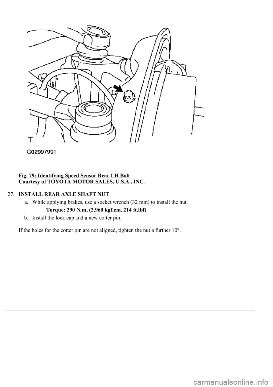
Fig. 79: Identifying Speed Sensor Rear LH Bolt
Courtesy of TOYOTA MOTOR SALES, U.S.A., INC.
27.INSTALL REAR AXLE SHAFT NUT
a. While applying brakes, use a socket wrench (32 mm) to install the nut.
Torque: 290 N.m, (2,960 kgf.cm, 214 ft.lbf)
b. Install the lock cap and a new cotter pin.
If the holes for the cotter pin are not ali
gned, tighten the nut a further 10°.
Page 2433 of 4500
dynamic laser cruise control system.
Operation of the constant speed control mode is the same as that for the conventional type
cruise control system.
b. This system maintains the vehicle running at the speed that the driver has set, as long as there are
no vehicles ahead in the same lane. Then, the system maintains the vehicle distance that has been
set by the driver.
If the system detects a vehicle moving at a slower speed ahead while the driver is driving at a
constant speed, it closes the throttle valve to decelerate. If further deceleration is required, the
system controls the brake actuator in order to apply the brakes. Thereafter, if there are no vehicles
ahead within the set vehicle-to-vehicle distance because either the vehicle ahead or the driver has
changed lanes, the system accelerates slowly to reach the set vehicle speed and resumes driving at
the constant speed.
c. The constant speed control mode is designed to maintain a constant cruising speed. The vehicle-to-
vehicle distance control mode is designed to control cruising at a constant speed function,
deceleration cruising function, follow-up cruising function and acceleration cruising function.
d. The laser sensor and the distance control ECU (cruise control ECU) control the system while the
vehicle-to-vehicle distance control mode is in operation, and send signals to each actuator and
ECU.
e. In vehicle-to-vehicle distance control mode, the dynamic laser cruise control system receives
signals from the yaw rate & deceleration sensor and the steering angle sensor. Based on these
signals, it then estimates curve radius and compensates for information on the preceding vehicle
while turning. It can also compensate for the brake control when approaching another vehicle.
f. This system judges the existence of a vehicle in front and the distance to it based on the signals
from the laser sensor while the vehicle-to-vehicle distance control mode is in operation. Using this
information, the system informs the driver of any danger with the warning buzzer, performs brake
control, and turns on the stop lamp when approaching the vehicle in front.
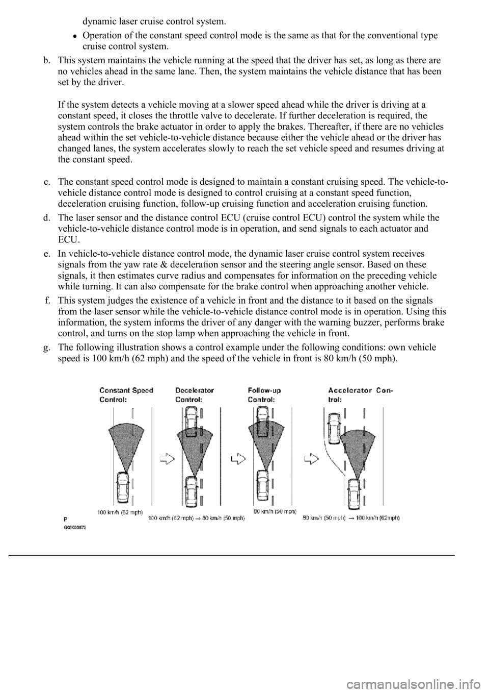
g. The following illustration shows a control example under the following conditions: own vehicle
speed is 100 km/h (62 mph) and the speed of the vehicle in front is 80 km/h (50 mph).
Page 2532 of 4500
1.GENERAL
a. The dynamic radar cruise control system has two cruise control modes: the constant speed control
mode and vehicle-to-vehicle distance control mode.
The vehicle-to-vehicle distance control mode is always selected when starting up the
dynamic radar cruise control system.
Operation of the constant speed control mode is the same as that for the conventional type
cruise control system.
b. This system maintains the vehicle running at the speed that the driver has set, as long as there are
no vehicles ahead in the same lane. Then, the system maintains the vehicle distance that has been
set by the driver.
If the system detects a vehicle moving at a slower speed ahead while the driver is driving at a
constant speed, it closes the throttle valve to decelerate. If further deceleration is required, the
system controls the brake actuator in order to apply the brakes. Thereafter, if there are no vehicles
ahead within the set vehicle-to-vehicle distance because either the vehicle ahead or the driver has
changed lanes, the system accelerates slowly to reach the set vehicle speed and resumes driving at
the constant speed.
c. The constant speed control mode is designed to maintain a constant cruising speed. The vehicle-to-
vehicle distance control mode is designed to control cruising at a constant speed function,
deceleration cruising function, follow-up cruising function and acceleration cruising function.
d. The millimeter wave radar sensor and the distance control ECU (cruise control ECU) control the
system while the vehicle-to-vehicle distance control mode is in operation, and send signals to each
actuator and ECU.
e. In vehicle-to-vehicle distance control mode, the dynamic radar cruise control system receives
signals from the yaw rate & deceleration sensor and the steering angle sensor. Based on these
signals, it then estimates curve radius and compensates for information on the preceding vehicle
while turning. It can also compensate for the brake control when approaching another vehicle.
f. This system judges the existence of a vehicle in front and the distance to it based on the signals
from the radar sensor while the vehicle-to-vehicle distance control mode is in operation. Using this
information, the system informs the driver of any danger with the warning buzzer, performs brake
control, and turns on the stop lamp when approaching the vehicle in front.
g. The following illustration shows a control example under the following conditions: own vehicle
speed is 100 km/h (62 mph) and the speed of the vehicle in front is 80 km/h (50 mph).
Page 2759 of 4500
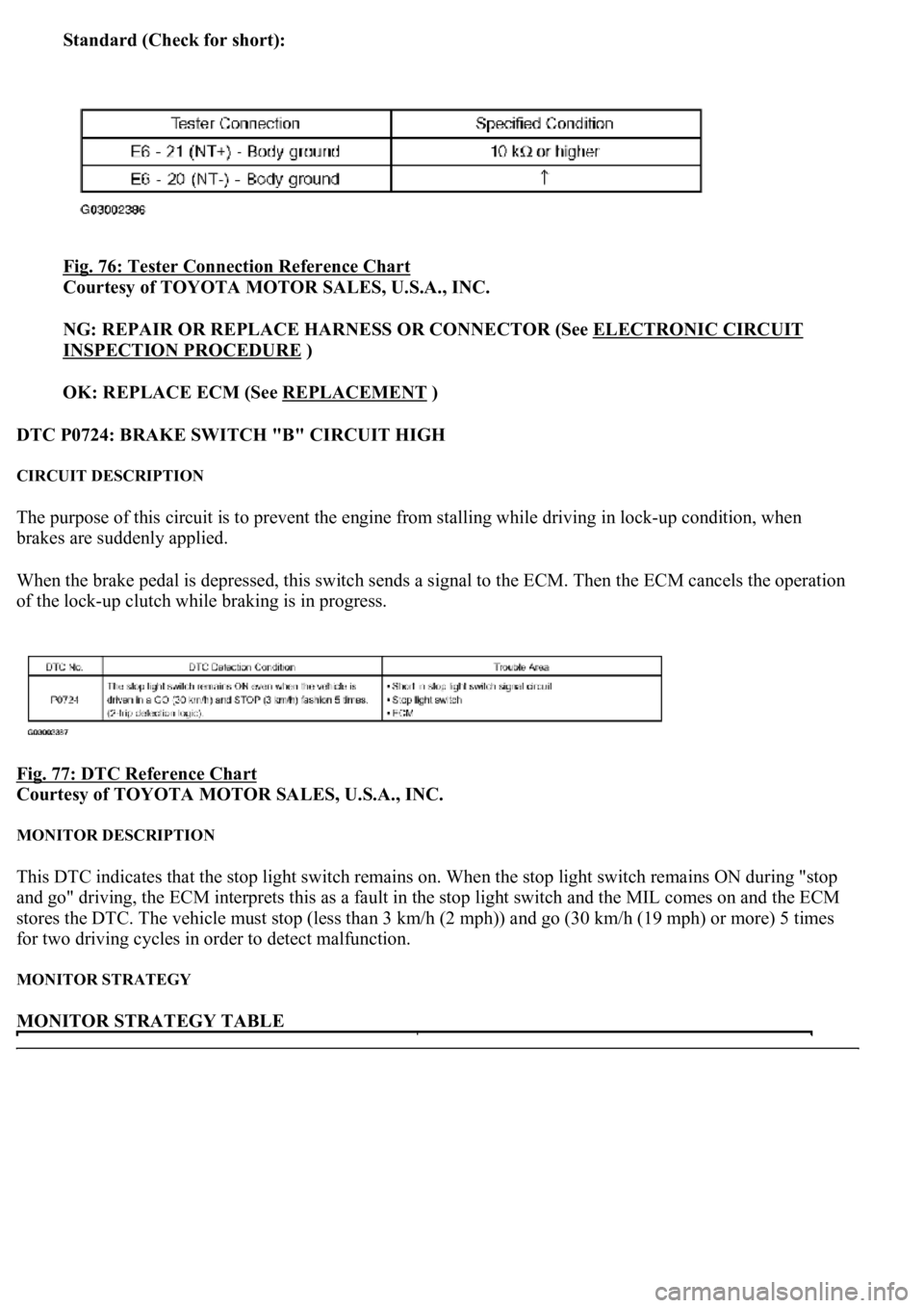
Standard (Check for short):
Fig. 76: Tester Connection Reference Chart
Courtesy of TOYOTA MOTOR SALES, U.S.A., INC.
NG: REPAIR OR REPLACE HARNESS OR CONNECTOR (See ELECTRONIC CIRCUIT
INSPECTION PROCEDURE )
OK: REPLACE ECM (See REPLACEMENT
)
DTC P0724: BRAKE SWITCH "B" CIRCUIT HIGH
CIRCUIT DESCRIPTION
The purpose of this circuit is to prevent the engine from stalling while driving in lock-up condition, when
brakes are suddenly applied.
When the brake pedal is depressed, this switch sends a signal to the ECM. Then the ECM cancels the operation
of the lock-up clutch while braking is in progress.
Fig. 77: DTC Reference Chart
Courtesy of TOYOTA MOTOR SALES, U.S.A., INC.
MONITOR DESCRIPTION
This DTC indicates that the stop light switch remains on. When the stop light switch remains ON during "stop
and go" driving, the ECM interprets this as a fault in the stop light switch and the MIL comes on and the ECM
stores the DTC. The vehicle must stop (less than 3 km/h (2 mph)) and go (30 km/h (19 mph) or more) 5 times
for two driving cycles in order to detect malfunction.
MONITOR STRATEGY
MONITOR STRATEGY TABLE
Page 2820 of 4500
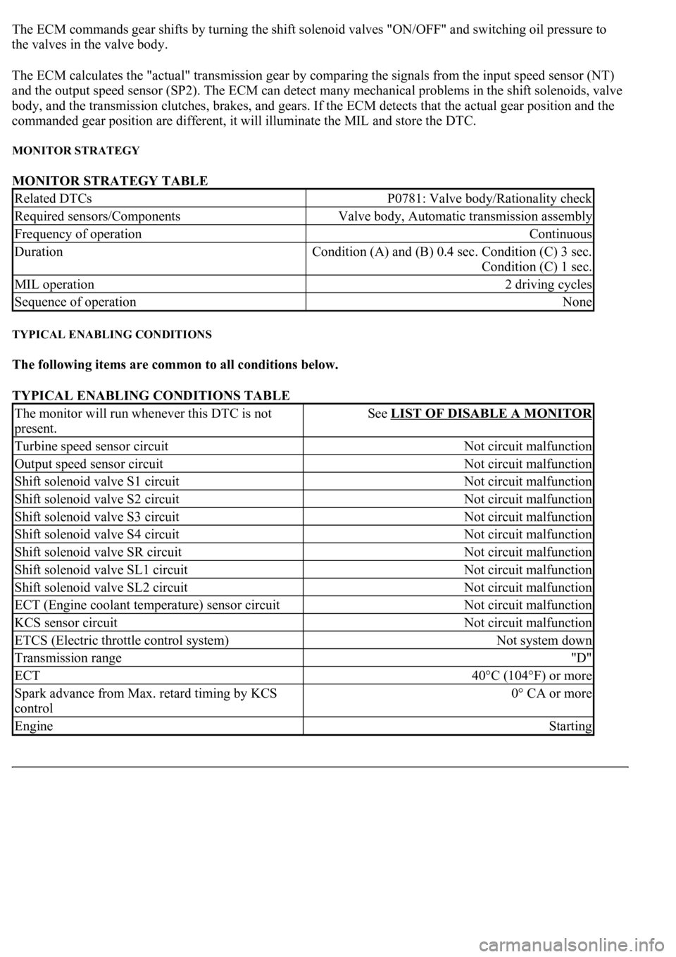
The ECM commands gear shifts by turning the shift solenoid valves "ON/OFF" and switching oil pressure to
the valves in the valve body.
The ECM calculates the "actual" transmission gear by comparing the signals from the input speed sensor (NT)
and the output speed sensor (SP2). The ECM can detect many mechanical problems in the shift solenoids, valve
body, and the transmission clutches, brakes, and gears. If the ECM detects that the actual gear position and the
commanded gear position are different, it will illuminate the MIL and store the DTC.
MONITOR STRATEGY
MONITOR STRATEGY TABLE
TYPICAL ENABLING CONDITIONS
The following items are common to all conditions below.
TYPICAL ENABLING CONDITIONS TABLE
Related DTCsP0781: Valve body/Rationality check
Required sensors/ComponentsValve body, Automatic transmission assembly
Frequency of operationContinuous
Duration<0026005200510047004c0057004c005200510003000b0024000c00030044005100470003000b0025000c00030013001100170003005600480046001100030026005200510047004c0057004c005200510003000b0026000c00030016000300560048004600
110003[
Condition (C) 1 sec.
MIL operation2 driving cycles
Sequence of operationNone
The monitor will run whenever this DTC is not
present.See LIST OF DISABLE A MONITOR
Turbine speed sensor circuitNot circuit malfunction
Output speed sensor circuitNot circuit malfunction
Shift solenoid valve S1 circuitNot circuit malfunction
Shift solenoid valve S2 circuitNot circuit malfunction
Shift solenoid valve S3 circuitNot circuit malfunction
Shift solenoid valve S4 circuitNot circuit malfunction
Shift solenoid valve SR circuitNot circuit malfunction
Shift solenoid valve SL1 circuitNot circuit malfunction
Shift solenoid valve SL2 circuitNot circuit malfunction
ECT (Engine coolant temperature) sensor circuitNot circuit malfunction
KCS sensor circuitNot circuit malfunction
ETCS (Electric throttle control system)Not system down
Transmission range"D"
ECT40°C (104°F) or more
Spark advance from Max. retard timing by KCS
control0° CA or more
EngineStarting