Page 85 of 4500
Fig. 61: SFL Solenoid Wiring Diagram
Courtesy of TOYOTA MOTOR SALES, U.S.A., INC.
INSPECTION PROCEDURE
1.RECONFIRM DTC
HINT:
This code is detected when a problem is determined in the brake actuator assy.
The ABS solenoid circuit is in the brake actuator assy. Therefore, solenoid circuit inspection relay unit
inspection cannot be performed. Be sure to check if the DTC code is output before replacing the brake
actuator assy.
a. Clear the DTC (see DTC CHECK/CLEAR
).
b. Start the engine.
c. Drive the vehicle at the speed of 4 mph (6 km/h) or more.
d. Check that the same DTC is recorded.
Page 86 of 4500

OK: Go to next step
The same DTC is recorded.
NG: PROCEED TO NEXT CIRCUIT INSPECTION SHOWN IN PROBLEM SYMPTOMS
TABLE
OK: REPLACE ABS & TRACTION ACTUATOR ASSY (SEE REPLACEMENT
)
CIRCUIT DESCRIPTION
The ABS motor relays consist of 2 relays are included in the engine room No.3 R/B.
The ABS cut relay is turned on after turning the ignition switch to the ON position. If the DTCs in the
ABS pump motor circuit are memorized, the ABS cut relay cuts off the power supply to the ABS motor
relay and performs the fail safe.
While any of the ABS, BA, TRAC and VSC is operating, the skid control ECU (included in the actuator)
<0057005800550051005600030057004b00480003002400250036000300500052005700520055000300550048004f0044005c0003005200510003005700520003005200530048005500440057004800030057004b0048000300440046005700580044005700
52005500030053005800500053000300500052005700520055[.
If the voltage applied to the ABS motor relays (+BM) drops below the condition that detects the DTCs
due to the shorta
ge of the battery or alternator output, the DTCs may be memorized.
Page 102 of 4500
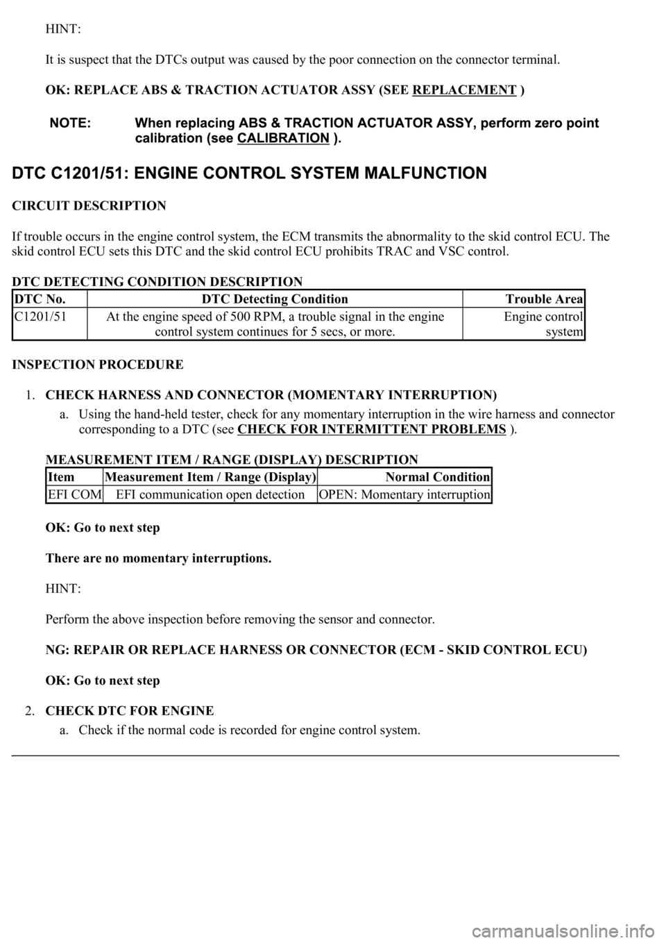
HINT:
It is suspect that the DTCs output was caused by the poor connection on the connector terminal.
OK: REPLACE ABS & TRACTION ACTUATOR ASSY (SEE REPLACEMENT
)
CIRCUIT DESCRIPTION
If trouble occurs in the engine control system, the ECM transmits the abnormality to the skid control ECU. The
skid control ECU sets this DTC and the skid control ECU prohibits TRAC and VSC control.
DTC DETECTING CONDITION DESCRIPTION
INSPECTION PROCEDURE
1.CHECK HARNESS AND CONNECTOR (MOMENTARY INTERRUPTION)
a. Using the hand-held tester, check for any momentary interruption in the wire harness and connector
corresponding to a DTC (see CHECK FOR INTERMITTENT PROBLEMS
).
MEASUREMENT ITEM / RANGE (DISPLAY) DESCRIPTION
OK: Go to next step
There are no momentary interruptions.
HINT:
Perform the above inspection before removing the sensor and connector.
NG: REPAIR OR REPLACE HARNESS OR CONNECTOR (ECM - SKID CONTROL ECU)
OK: Go to next step
2.CHECK DTC FOR ENGINE
a. Check if the normal code is recorded for en
gine control system.
DTC No.DTC Detecting ConditionTrouble Area
C1201/51At the engine speed of 500 RPM, a trouble signal in the engine
control system continues for 5 secs, or more.Engine control
system
ItemMeasurement Item / Range (Display)Normal Condition
EFI COMEFI communication open detectionOPEN: Momentary interruption
Page 125 of 4500
OK: Go to next step
2.INSPECT BATTERY
a. Check the battery voltage.
Standard:
Voltage: 10 to 14 V
NG: INSPECT CHARGING SYSTEM (SEE ON
-VEHICLE INSPECTION )
OK: Go to next step
3.INSPECT SKID CONTROL ECU TERMINAL VOLTAGE (IG1 TERMINAL)
a. Connect the hand-held tester to the DLC3.
b. Start the engine.
c. Select the DATA LIST mode on the hand-held tester.
Fig. 91: DATA LIST Mode Description
Courtesy of TOYOTA MOTOR SALES, U.S.A., INC.
d. Read the voltage condition output from the ECU displayed on the hand-held tester.
Standard:
"Normal" is displayed.
NG: Go to step 4
OK: REPLACE ABS & TRACTION ACTUATOR ASSY (SEE REPLACEMENT
)
4.INSPECT SKID CONTROL ECU CONNECTOR (GND TERMINAL CONTINUITY)
a. Disconnect the skid control ECU connector.
b. Measure the resistance according to the value (s) in the table below.
Standard:
Page 154 of 4500
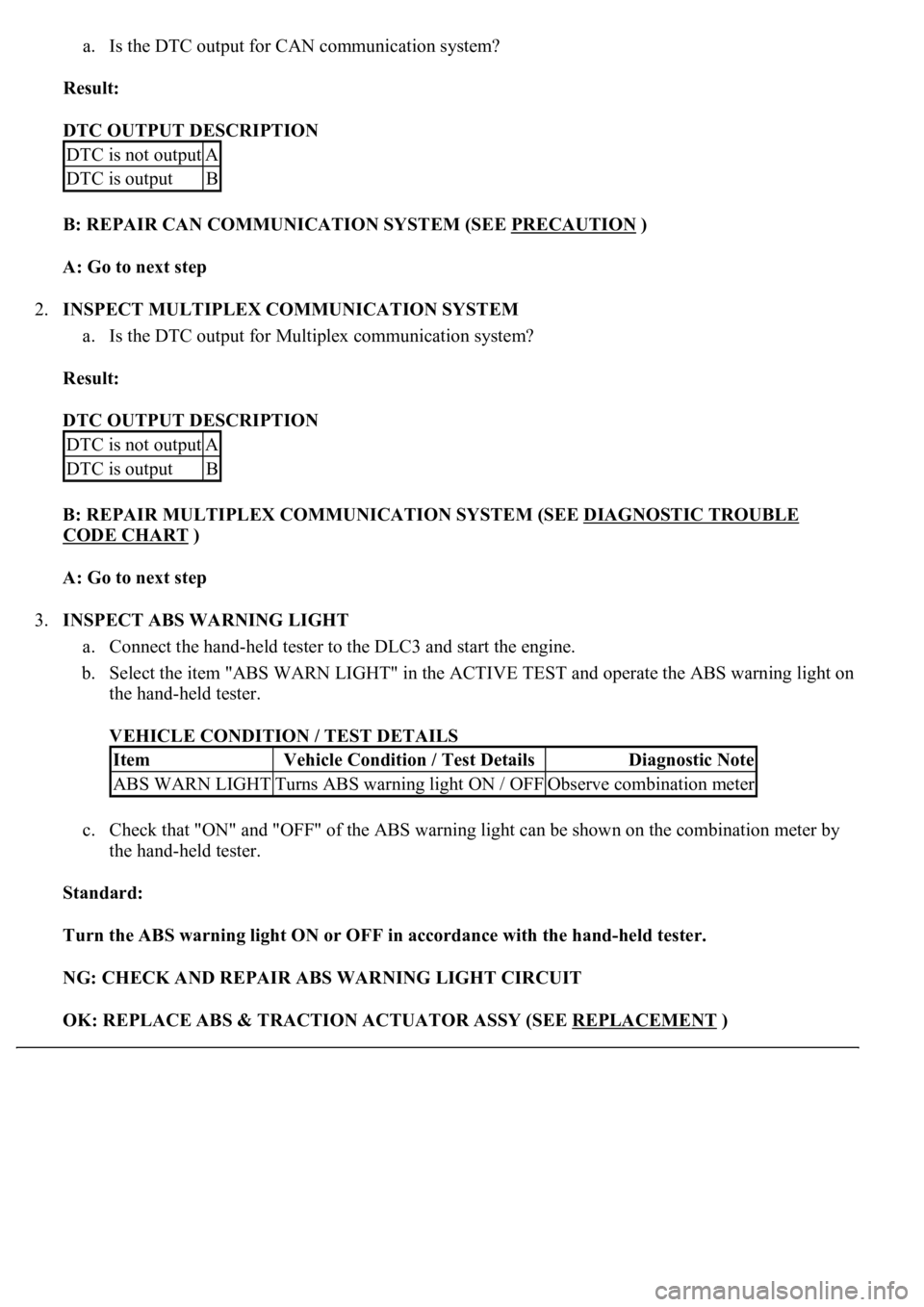
a. Is the DTC output for CAN communication system?
Result:
DTC OUTPUT DESCRIPTION
B: REPAIR CAN COMMUNICATION SYSTEM (SEE PRECAUTION
)
A: Go to next step
2.INSPECT MULTIPLEX COMMUNICATION SYSTEM
a. Is the DTC output for Multiplex communication system?
Result:
DTC OUTPUT DESCRIPTION
B: REPAIR MULTIPLEX COMMUNICATION SYSTEM (SEE DIAGNOSTIC TROUBLE
CODE CHART )
A: Go to next step
3.INSPECT ABS WARNING LIGHT
a. Connect the hand-held tester to the DLC3 and start the engine.
b. Select the item "ABS WARN LIGHT" in the ACTIVE TEST and operate the ABS warning light on
the hand-held tester.
VEHICLE CONDITION / TEST DETAILS
c. Check that "ON" and "OFF" of the ABS warning light can be shown on the combination meter by
the hand-held tester.
Standard:
Turn the ABS warning light ON or OFF in accordance with the hand-held tester.
NG: CHECK AND REPAIR ABS WARNING LIGHT CIRCUIT
OK: REPLACE ABS & TRACTION ACTUATOR ASSY (SEE REPLACEMENT
)
DTC is not outputA
DTC is outputB
DTC is not outputA
DTC is outputB
ItemVehicle Condition / Test DetailsDiagnostic Note
ABS WARN LIGHTTurns ABS warning light ON / OFFObserve combination meter
Page 161 of 4500
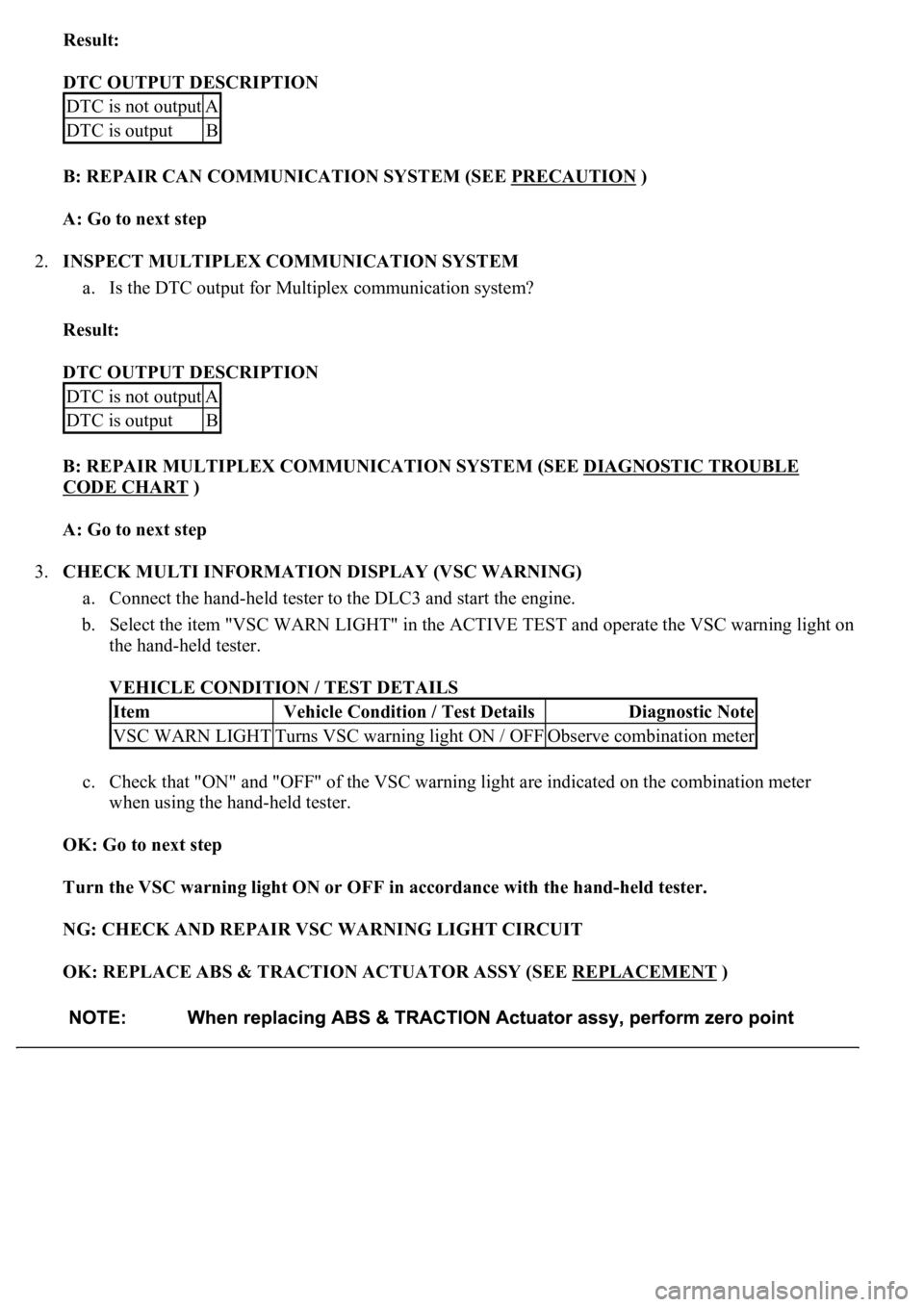
Result:
DTC OUTPUT DESCRIPTION
B: REPAIR CAN COMMUNICATION SYSTEM (SEE PRECAUTION
)
A: Go to next step
2.INSPECT MULTIPLEX COMMUNICATION SYSTEM
a. Is the DTC output for Multiplex communication system?
Result:
DTC OUTPUT DESCRIPTION
B: REPAIR MULTIPLEX COMMUNICATION SYSTEM (SEE DIAGNOSTIC TROUBLE
CODE CHART )
A: Go to next step
3.CHECK MULTI INFORMATION DISPLAY (VSC WARNING)
a. Connect the hand-held tester to the DLC3 and start the engine.
b. Select the item "VSC WARN LIGHT" in the ACTIVE TEST and operate the VSC warning light on
the hand-held tester.
VEHICLE CONDITION / TEST DETAILS
c. Check that "ON" and "OFF" of the VSC warning light are indicated on the combination meter
when using the hand-held tester.
OK: Go to next step
Turn the VSC warning light ON or OFF in accordance with the hand-held tester.
NG: CHECK AND REPAIR VSC WARNING LIGHT CIRCUIT
OK: REPLACE ABS & TRACTION ACTUATOR ASSY (SEE REPLACEMENT
)
DTC is not outputA
DTC is outputB
DTC is not outputA
DTC is outputB
ItemVehicle Condition / Test DetailsDiagnostic Note
VSC WARN LIGHTTurns VSC warning light ON / OFFObserve combination meter
Page 183 of 4500
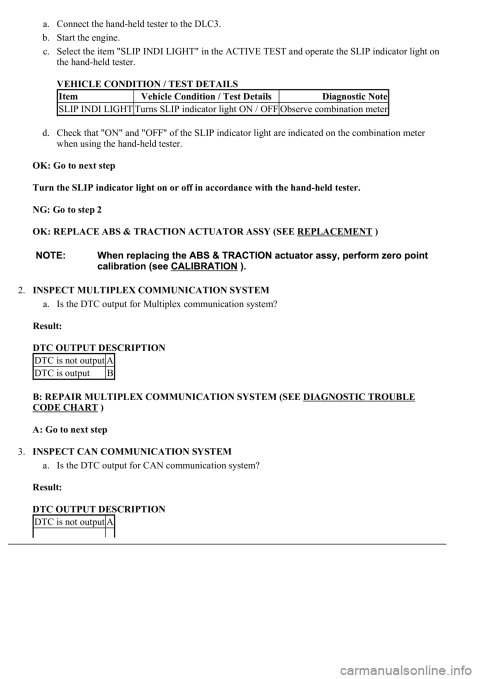
a. Connect the hand-held tester to the DLC3.
b. Start the engine.
c. Select the item "SLIP INDI LIGHT" in the ACTIVE TEST and operate the SLIP indicator light on
the hand-held tester.
VEHICLE CONDITION / TEST DETAILS
d. Check that "ON" and "OFF" of the SLIP indicator light are indicated on the combination meter
when using the hand-held tester.
OK: Go to next step
Turn the SLIP indicator light on or off in accordance with the hand-held tester.
NG: Go to step 2
OK: REPLACE ABS & TRACTION ACTUATOR ASSY (SEE REPLACEMENT
)
2.INSPECT MULTIPLEX COMMUNICATION SYSTEM
a. Is the DTC output for Multiplex communication system?
Result:
DTC OUTPUT DESCRIPTION
B: REPAIR MULTIPLEX COMMUNICATION SYSTEM (SEE DIAGNOSTIC TROUBLE
CODE CHART )
A: Go to next step
3.INSPECT CAN COMMUNICATION SYSTEM
a. Is the DTC output for CAN communication system?
Result:
DTC OUTPUT DESCRIPTION
ItemVehicle Condition / Test DetailsDiagnostic Note
SLIP INDI LIGHTTurns SLIP indicator light ON / OFFObserve combination meter
DTC is not outputA
DTC is outputB
DTC is not outputA
Page 495 of 4500

Fig. 17: Diagnostic Trouble Code Information Chart (2 Of 2)
Courtesy of TOYOTA MOTOR SALES, U.S.A., INC.
*1: For codes in the "Indicator Light" column with a "circ" mark, the absorber control indicator lamp blinks at 1
second intervals.
*2: For codes in the "Indicator Light" column with a " (xcirc)" mark, when trouble occurs, "HEIGHT HI" is
displayed on the multi-information display. Also, the master warning light is lit on the combination meter and
an alarm sounds.
*3: Since the relief pressure of the compressed air is 980 kPa (10 kgf/cm
2 , 142 psi), if vehicle height control is
attempted on a steeply sloping road, when the vehicle is overloaded, or when the vehicle height is jacked up
with the engine running, code "C1751" may be output and vehicle height control may be suspended. (This is not
abnormal.) In this case, however, when detecting the first error, approximately 10 minutes after the ignition
switch was turned to the ON position, vehicle height control is resumed. When the following errors are
detected, it takes 70 minutes until the control is resumed.
*4: If vehicle height control is operated while the wheels are removed or the vehicle is jacked up, code "C1752"
may be output, but this is not abnormal. When code "C1752" is output, vehicle height control is not carried out.
However, control is resumed if the ignition switch is turned off, then to the ON position again.
CIRCUIT DESCRIPTION
The height control sensor sub-assy controls the resistance value by following changes in vehicle height. The
suspension control ECU detects the change in vehicle height from the transformed voltage. The suspension
control ECU outputs a constant voltage of 5 V to the SHB terminal of the height control sensor sub-assy.
In the height control sensor, the voltage is changed due to resistance. The changed voltage is output from the

