Page 2031 of 4500

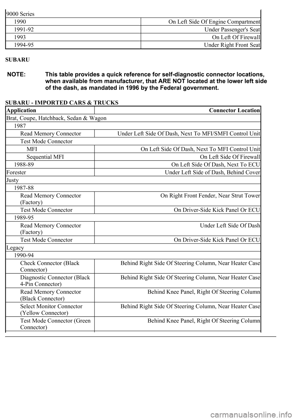
SUBARU
SUBARU - IMPORTED CARS & TRUCKS
9000 Series
1990On Left Side Of Engine Compartment
1991-92Under Passenger's Seat
1993On Left Of Firewall
1994-95Under Right Front Seat
ApplicationConnector Location
Brat, Coupe, Hatchback, Sedan & Wagon
1987
Read Memory ConnectorUnder Left Side Of Dash, Next To MFI/SMFI Control Unit
Test Mode Connector
MFIOn Left Side Of Dash, Next To MFI Control Unit
Sequential MFIOn Left Side Of Firewall
1988-89On Left Side Of Dash, Next To ECU
ForesterUnder Left Side of Dash, Behind Cover
Justy
1987-88
Read Memory Connector
(Factory)On Right Front Fender, Near Strut Tower
Test Mode ConnectorOn Driver-Side Kick Panel Or ECU
1989-95
Read Memory Connector
(Factory)Under Left Side Of Dash
Test Mode ConnectorOn Driver-Side Kick Panel Or ECU
Legacy
1990-94
Check Connector (Black
Connector)Behind Right Side Of Steering Column, Near Heater Case
Diagnostic Connector (Black
4-Pin Connector)Behind Right Side Of Steering Column, Near Heater Case
Read Memory Connector
(Black Connector)Behind Knee Panel, Right Of Steering Column
Select Monitor Connector
(Yellow Connector)Behind Right Side Of Steering Column, Near Heater Case
Test Mode Connector (Green
Connector)Behind Knee Panel, Right Of Steering Column
Page 3029 of 4500
Fig. 45: Removing Inside Handle
Courtesy of TOYOTA MOTOR SALES, U.S.A., INC.
h. Using a screwdriver, disengage the 2 clips and remove the courtesy lamp.
i. Remove the 2 screws and seat memory switch.
j. Remove the 3 screws and vent seal.
k. Remove the 2 screws and door pocket.
Page 3085 of 4500
Fig. 98: Disconnecting Cables From Inside Handle
Courtesy of TOYOTA MOTOR SALES, U.S.A., INC.
d. Remove the screw.
e. Using a screwdriver, disengage the 2 claws and remove the inside door handle.
HINT:
Tape the screwdriver tip before use.
f. Remove the No. 1 illumination lamp.
g. w/ Seat memory:
Remove the seat memory switch.
Page 3086 of 4500
Fig. 99: Removing Seat Memory Switch
Courtesy of TOYOTA MOTOR SALES, U.S.A., INC.
h. w/ Rear side curtain:
Remove the 4 screws and curtain.
Page 3915 of 4500

Fig. 4: Communication Table
Courtesy of TOYOTA MOTOR SALES, U.S.A., INC.
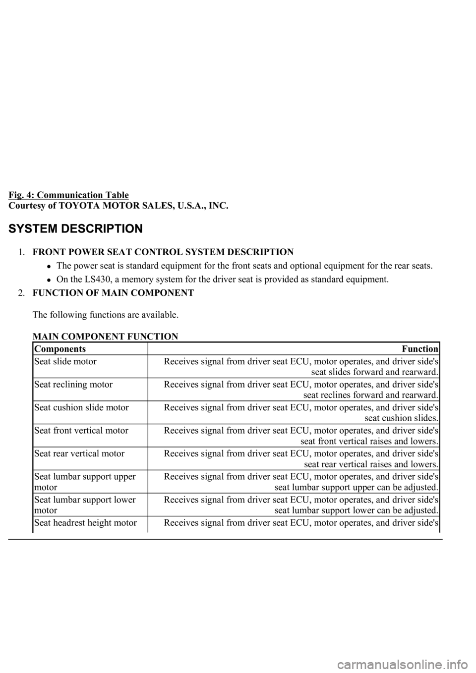
1.FRONT POWER SEAT CONTROL SYSTEM DESCRIPTION
The power seat is standard equipment for the front seats and optional equipment for the rear seats.
On the LS430, a memory system for the driver seat is provided as standard equipment.
2.FUNCTION OF MAIN COMPONENT
The following functions are available.
MAIN COMPONENT FUNCTION
ComponentsFunction
Seat slide motorReceives signal from driver seat ECU, motor operates, and driver side's
seat slides forward and rearward.
Seat reclining motorReceives signal from driver seat ECU, motor operates, and driver side's
seat reclines forward and rearward.
Seat cushion slide motorReceives signal from driver seat ECU, motor operates, and driver side's
seat cushion slides.
Seat front vertical motorReceives signal from driver seat ECU, motor operates, and driver side's
seat front vertical raises and lowers.
Seat rear vertical motorReceives signal from driver seat ECU, motor operates, and driver side's
seat rear vertical raises and lowers.
Seat lumbar support upper
motorReceives signal from driver seat ECU, motor operates, and driver side's
seat lumbar support upper can be adjusted.
Seat lumbar support lower
motorReceives signal from driver seat ECU, motor operates, and driver side's
seat lumbar support lower can be adjusted.
Seat headrest height motorReceives signal from driver seat ECU, motor operates, and driver side's
Page 3916 of 4500

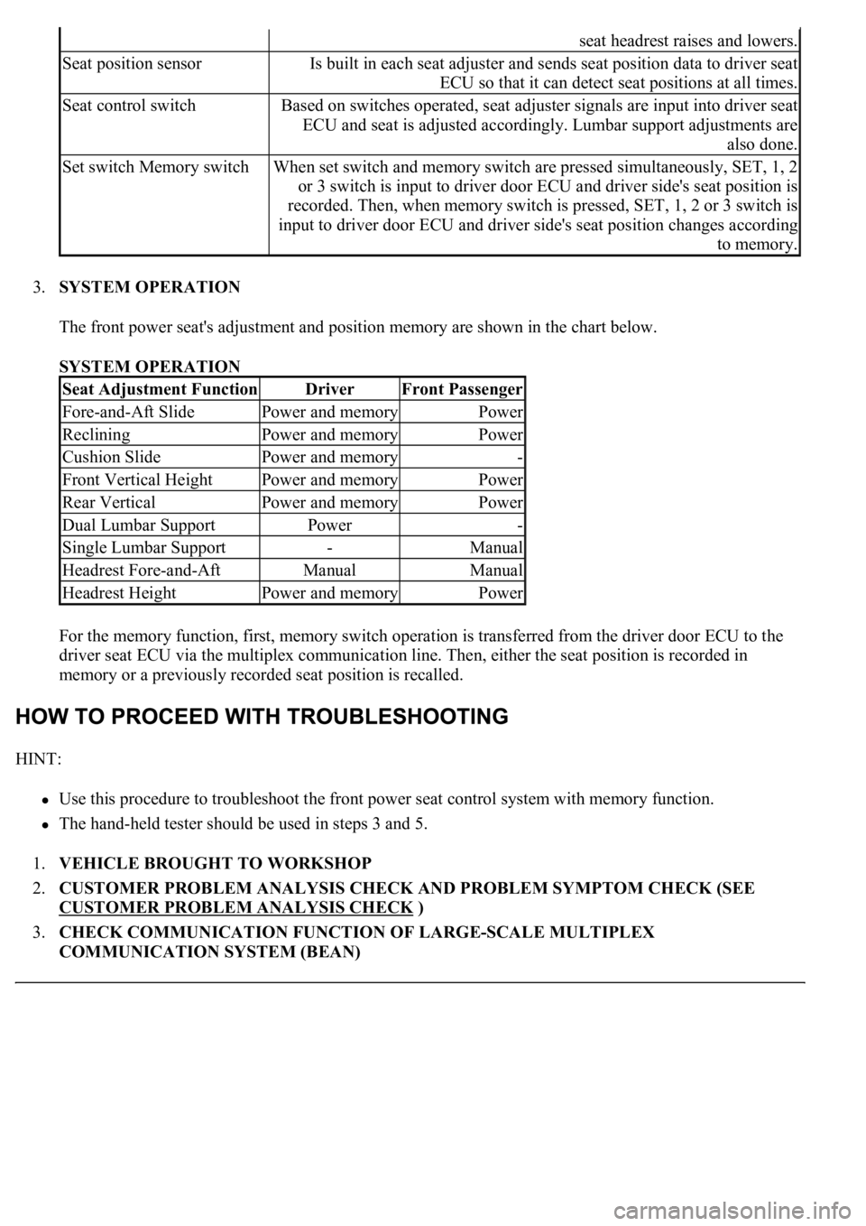
3.SYSTEM OPERATION
The front power seat's adjustment and position memory are shown in the chart below.
SYSTEM OPERATION
For the memory function, first, memory switch operation is transferred from the driver door ECU to the
driver seat ECU via the multiplex communication line. Then, either the seat position is recorded in
memory or a previously recorded seat position is recalled.
HINT:
Use this procedure to troubleshoot the front power seat control system with memory function.
<0037004b00480003004b0044005100470010004b0048004f0047000300570048005600570048005500030056004b00520058004f0047000300450048000300580056004800470003004c005100030056005700480053005600030016000300440051004700
030018001100030003[
1.VEHICLE BROUGHT TO WORKSHOP
2.CUSTOMER PROBLEM ANALYSIS CHECK AND PROBLEM SYMPTOM CHECK (SEE
CUSTOMER PROBLEM ANALYSIS CHECK
)
3.CHECK COMMUNICATION FUNCTION OF LARGE-SCALE MULTIPLEX
COMMUNICATION SYSTEM (BEAN)
seat headrest raises and lowers.
Seat position sensorIs built in each seat adjuster and sends seat position data to driver seat
ECU so that it can detect seat positions at all times.
Seat control switchBased on switches operated, seat adjuster signals are input into driver seat
ECU and seat is adjusted accordingly. Lumbar support adjustments are
also done.
Set switch Memory switchWhen set switch and memory switch are pressed simultaneously, SET, 1, 2
or 3 switch is input to driver door ECU and driver side's seat position is
recorded. Then, when memory switch is pressed, SET, 1, 2 or 3 switch is
input to driver door ECU and driver side's seat position changes according
to memory.
Seat Adjustment FunctionDriverFront Passenger
Fore-and-Aft SlidePower and memoryPower
RecliningPower and memoryPower
Cushion SlidePower and memory-
Front Vertical HeightPower and memoryPower
Rear VerticalPower and memoryPower
Dual Lumbar SupportPower-
Single Lumbar Support-Manual
Headrest Fore-and-AftManualManual
Headrest HeightPower and memoryPower
Page 3924 of 4500

If the result is not as specified, replace the driver door ECU may have a malfunction.
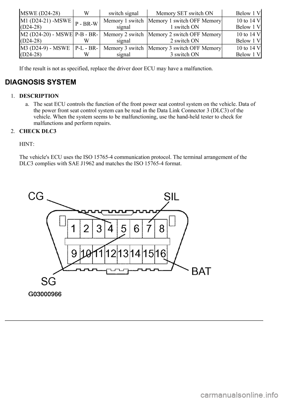
1.DESCRIPTION
a. The seat ECU controls the function of the front power seat control system on the vehicle. Data of
the power front seat control system can be read in the Data Link Connector 3 (DLC3) of the
vehicle. When the system seems to be malfunctioning, use the hand-held tester to check for
malfunctions and perform repairs.
2.CHECK DLC3
HINT:
The vehicle's ECU uses the ISO 15765-4 communication protocol. The terminal arrangement of the
DLC3 complies with SAE J1962 and matches the ISO 15765-4 format.
MSWE (D24-28)Wswitch signalMemory SET switch ONBelow 1 V
M1 (D24-21) -MSWE
(D24-28)P - BR-WMemory 1 switch
signalMemory 1 switch OFF Memory
1 switch ON10 to 14 V
Below 1 V
M2 (D24-20) - MSWE
(D24-28)P-B - BR-
WMemory 2 switch
signalMemory 2 switch OFF Memory
2 switch ON10 to 14 V
Below 1 V
M3 (D24-9) - MSWE
(D24-28)P-L - BR-
WMemory 3 switch
signalMemory 3 switch OFF Memory
3 switch ON10 to 14 V
Below 1 V
Page 3942 of 4500
Fig. 22: Identifying D27 Driver Seat ECU Connector Terminals And Power Seat Motor Connector
Terminals
Courtesy of TOYOTA MOTOR SALES, U.S.A., INC.
NG: REPAIR OR REPLACE WIRE HARNESS AND CONNECTOR
OK: PROCEED TO NEXT CIRCUIT INSPECTION SHOWN ON PROBLEM SYMPTOMS
TABLE
CIRCUIT DESCRIPTION
The position sensor detects seat movement and sends pulse signals to the driver seat ECU for use with the
memory function.
The ECU records the number of pulses relative to a previously recorded seat position and uses this data to
return the seat to that position.
If a malfunction occurs in a position sensor and seat movement does not result in pulse signals being input into
the ECU, the memory function is deactivated.
WIRING DIAGRAM