Page 1 of 4500
LS430 SPECIFICATIONS INDEX
SystemSpecification/Procedure
Air Conditioning
ServiceSERVICE DATA
TorqueTORQUE SPECIFICATION
Axle Nut/Hub Nut
Front69 N.m (700 kgf.cm, 51 ft.lbf)
Rear290 N.m (2,960 kgf.cm, 214 ft.lbf)
BatteryNA
Brakes
Bleeding
SequenceBLEEDING
Disc BrakesSERVICE DATA
TorqueTORQUE SPECIFICATION
Charging
GeneratorSERVICE DATA
TorqueTORQUE SPECIFICATION
Drive Belts
AdjustmentREPLACEMENT
Belt RoutingDRIVE BELT
Engine Cooling
General Service
SpecificationsSERVICE DATA
Radiator Cap
PressureStandard Value
93 to 123 kPa (0.95 to 1.25 kgf/cm
2 , 13.5 to 17.8 psi)
Minimum Standard Value
78 kPa (0.8 kgf/cm
2 , 11.4 psi)
Thermostat R & ITHERMOSTAT
Water Pump R &
IWATER PUMP
Engine Mechanical
CompressionSERVICE DATA
Oil Pressureat idle, 29 kPa (0.3 kgf.cm2 , 43 psi) or more
at 3,000 rpm, 294 to 588 kPa (3.0 to 6.0 kgf.cm
2 , 43 to 85 psi)
OverhaulSERVICE DATA
TorqueTORQUE SPECIFICATION
Page 2681 of 4500
d. P position test:
Stop the vehicle on a grade (more than 5°) and after shifting into the P position, release the parking
brake. Then, check that the parking lock pawl holds the vehicle in place.
MECHANICAL SYSTEM TESTS
1.PERFORM MECHANICAL SYSTEM TESTS
a. Measure the stall speed.
The object of this test is to check the overall performance of the transmission and engine by
measuring the stall speeds in the D and R positions.
1. Chock the 4 wheels.
2. Connect an OBD II scan tool or hand-held tester to the DLC3.
3. Fully apply the parking brake.
4. Keep your left foot pressed firmly on the brake pedal.
5. Start the engine.
6. Shift into the D position. Press all the way down on the accelerator pedal with your right
foot.
7. Quickly read the stall speed at this time.
Stall speed: 2,400 +/- 150 rpm
8. Do the same test in the R position.
Stall speed: 2,400 +/- 150 rpm
Evaluation:
Page 2682 of 4500
Fig. 7: Mechanical Systems Problem Symptoms Chart
Courtesy of TOYOTA MOTOR SALES, U.S.A., INC.
b. Measure the time lag.
1. When the shift lever is shifted while the engine is idling, there will be a certain time lapse or
lag before the shock can be felt. This is used for checking the condition of the direct clutch,
forward clutch, and 1st and reverse brake.
2. Connect an OBD II scan tool or hand-held tester to the DLC3.
3. Fully apply the parking brake.
4. Start and warm up the engine and check idle speed.
Idle speed: approx. 700 rpm (In N position and A/C OFF)
5. Shift the lever from N to D position. Using a stop watch, measure the time from when the
lever is shifted until the shock is felt.
Time lag: N --> D less than 1.2 seconds
6. In the same way, measure the time lag for N --> R.
Time lag: N --> R less than 1.5 seconds
Evaluation (If N --> D or N --> R time lag is longer than the specified):
Page 2768 of 4500

a. Warm up the engine.
b. Turn the ignition switch off.
c. Connect the hand-held tester together with the CAN VIM (controller area network vehicle interface
module) to the DLC3.
d. Turn the ignition switch to the ON position.
e. Push the "ON" button of the hand-held tester.
f. Clear the DTC.
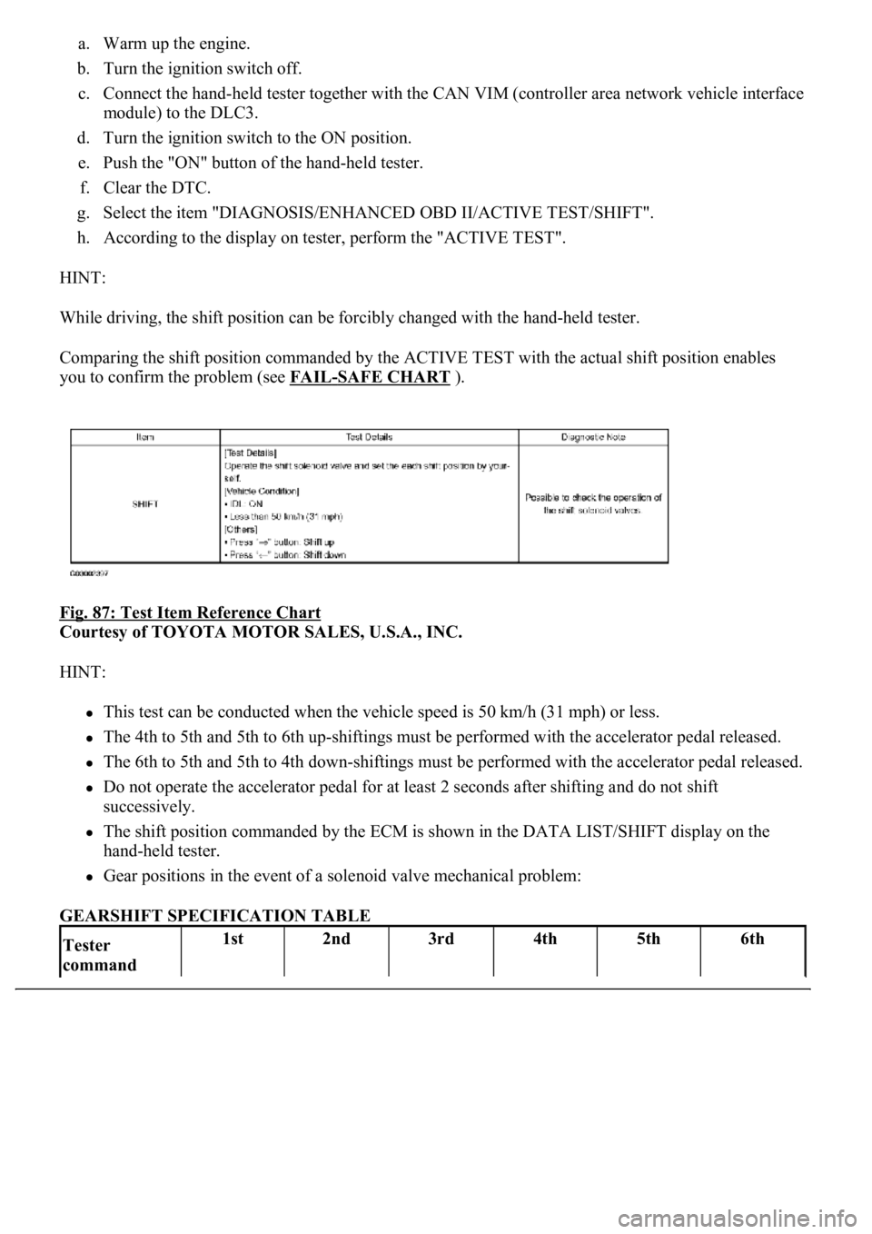
g. Select the item "DIAGNOSIS/ENHANCED OBD II/ACTIVE TEST/SHIFT".
h. According to the display on tester, perform the "ACTIVE TEST".
HINT:
While driving, the shift position can be forcibly changed with the hand-held tester.
Comparing the shift position commanded by the ACTIVE TEST with the actual shift position enables
you to confirm the problem (see FAIL
-SAFE CHART ).
Fig. 87: Test Item Reference Chart
Courtesy of TOYOTA MOTOR SALES, U.S.A., INC.
HINT:
This test can be conducted when the vehicle speed is 50 km/h (31 mph) or less.
The 4th to 5th and 5th to 6th up-shiftings must be performed with the accelerator pedal released.
The 6th to 5th and 5th to 4th down-shiftings must be performed with the accelerator pedal released.
Do not operate the accelerator pedal for at least 2 seconds after shifting and do not shift
successively.
The shift position commanded by the ECM is shown in the DATA LIST/SHIFT display on the
hand-held tester.
Gear positions in the event of a solenoid valve mechanical problem:
GEARSHIFT SPECIFICATION TABLE
Tester
command 1st2nd3rd4th5th6th
Page 2820 of 4500

The ECM commands gear shifts by turning the shift solenoid valves "ON/OFF" and switching oil pressure to
the valves in the valve body.
The ECM calculates the "actual" transmission gear by comparing the signals from the input speed sensor (NT)
and the output speed sensor (SP2). The ECM can detect many mechanical problems in the shift solenoids, valve
body, and the transmission clutches, brakes, and gears. If the ECM detects that the actual gear position and the
commanded gear position are different, it will illuminate the MIL and store the DTC.
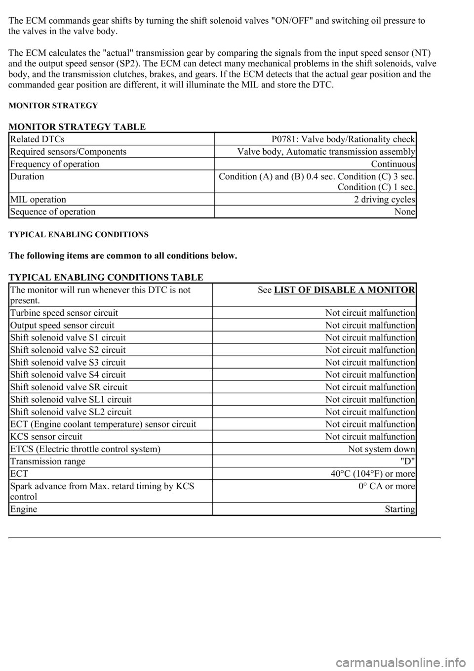
MONITOR STRATEGY
MONITOR STRATEGY TABLE
TYPICAL ENABLING CONDITIONS
The following items are common to all conditions below.
TYPICAL ENABLING CONDITIONS TABLE
Related DTCsP0781: Valve body/Rationality check
Required sensors/ComponentsValve body, Automatic transmission assembly
Frequency of operationContinuous
Duration<0026005200510047004c0057004c005200510003000b0024000c00030044005100470003000b0025000c00030013001100170003005600480046001100030026005200510047004c0057004c005200510003000b0026000c00030016000300560048004600
110003[
Condition (C) 1 sec.
MIL operation2 driving cycles
Sequence of operationNone
The monitor will run whenever this DTC is not
present.See LIST OF DISABLE A MONITOR
Turbine speed sensor circuitNot circuit malfunction
Output speed sensor circuitNot circuit malfunction
Shift solenoid valve S1 circuitNot circuit malfunction
Shift solenoid valve S2 circuitNot circuit malfunction
Shift solenoid valve S3 circuitNot circuit malfunction
Shift solenoid valve S4 circuitNot circuit malfunction
Shift solenoid valve SR circuitNot circuit malfunction
Shift solenoid valve SL1 circuitNot circuit malfunction
Shift solenoid valve SL2 circuitNot circuit malfunction
ECT (Engine coolant temperature) sensor circuitNot circuit malfunction
KCS sensor circuitNot circuit malfunction
ETCS (Electric throttle control system)Not system down
Transmission range"D"
ECT40°C (104°F) or more
Spark advance from Max. retard timing by KCS
control0° CA or more
EngineStarting
Page 2823 of 4500

method to shorten labor time.
It is possible to display the DATA LIST during the ACTIVE TEST.
a. Warm up the engine.
b. Turn the ignition switch off.
c. Connect the hand-held tester together with the CAN VIM (controller area network vehicle interface
module) to the DLC3.
d. Turn the ignition switch to the ON position.
e. Push the "ON" button of the hand-held tester.
f. Clear the DTC.
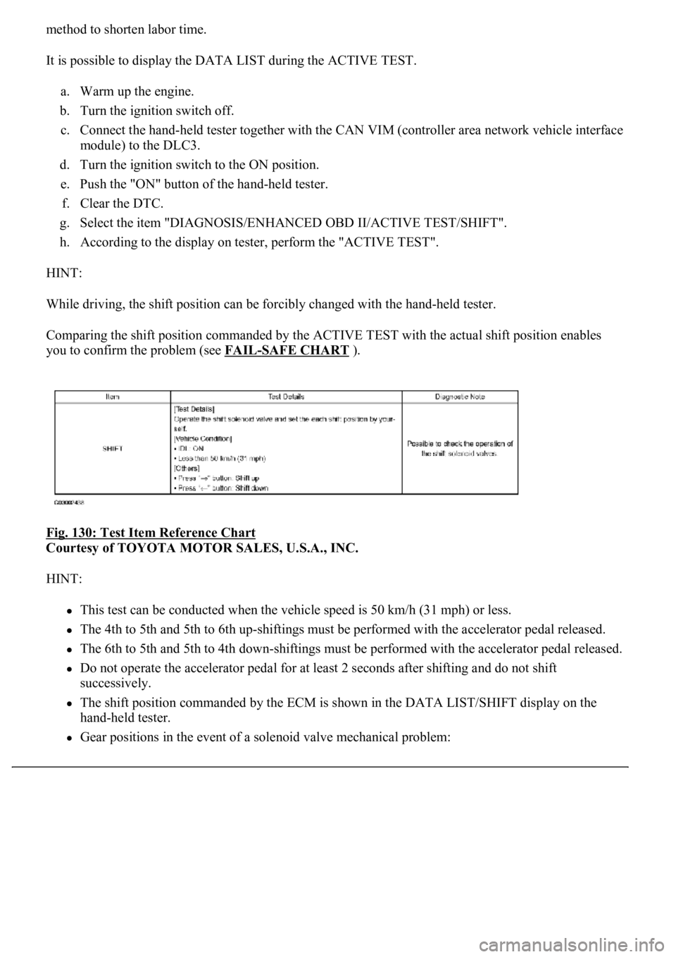
g. Select the item "DIAGNOSIS/ENHANCED OBD II/ACTIVE TEST/SHIFT".
h. According to the display on tester, perform the "ACTIVE TEST".
HINT:
While driving, the shift position can be forcibly changed with the hand-held tester.
Comparing the shift position commanded by the ACTIVE TEST with the actual shift position enables
you to confirm the problem (see FAIL
-SAFE CHART ).
Fig. 130: Test Item Reference Chart
Courtesy of TOYOTA MOTOR SALES, U.S.A., INC.
HINT:
This test can be conducted when the vehicle speed is 50 km/h (31 mph) or less.
The 4th to 5th and 5th to 6th up-shiftings must be performed with the accelerator pedal released.
The 6th to 5th and 5th to 4th down-shiftings must be performed with the accelerator pedal released.
Do not operate the accelerator pedal for at least 2 seconds after shifting and do not shift
successively.
The shift position commanded by the ECM is shown in the DATA LIST/SHIFT display on the
hand-held tester.
Gear positions in the event of a solenoid valve mechanical problem: