Page 703 of 4500
Fig. 1: Locating Audio System
Courtesy of TOYOTA MOTOR SALES, U.S.A., INC.
Page 704 of 4500
Fig. 2: Audio System Diagram
Courtesy of TOYOTA MOTOR SALES, U.S.A., INC.
Input and output signals of each ECU.
TRANSMITTING ECU (TRANSMITTER) CHART
1.CD (Compact Disc) player outline
a. A compact disc player uses a laser pickup to read digital signals recorded on a compact disc (CD).
Transmitting ECU
(Transmitter)
Receiving ECUSignalsCommunication method
Driver Side J/B ECUSteering Pad SwitchACC SW SignalBEAN (Column Bus)
Driver Side J/B ECUSteering Pad SwitchTaillight ON SignalBEAN (Column Bus)
Steering Pad SwitchRadio Receiver AssyAudio SignalBEAN (Column Bus) AVC-
LAN
Page 705 of 4500

By converting the digital signals to analog, it can play music and other things. In general, CD
players can play 4.7-inch (12 cm) or 3.2-inch (8 cm) disc.
HINT:
Do not disassemble any part of the CD player.
Do not apply oil to the CD player.
Do not insert anything but a CD into the CD player.
2.AVC-LAN Description
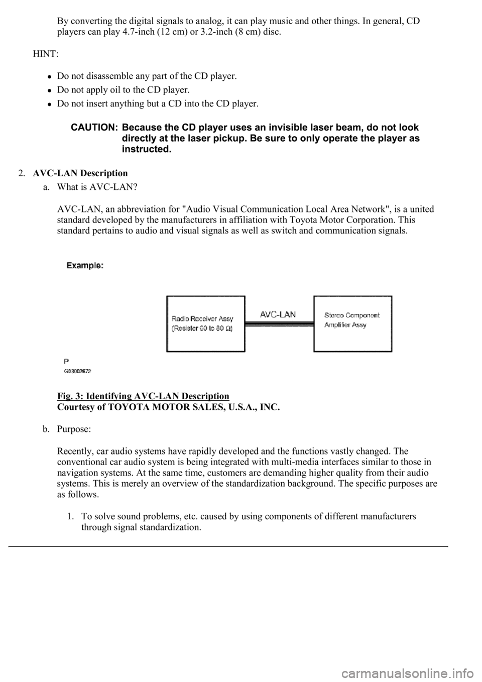
a. What is AVC-LAN?
AVC-LAN, an abbreviation for "Audio Visual Communication Local Area Network", is a united
standard developed by the manufacturers in affiliation with Toyota Motor Corporation. This
standard pertains to audio and visual signals as well as switch and communication signals.
Fig. 3: Identifying AVC
-LAN Description
Courtesy of TOYOTA MOTOR SALES, U.S.A., INC.
b. Purpose:
Recently, car audio systems have rapidly developed and the functions vastly changed. The
conventional car audio system is being integrated with multi-media interfaces similar to those in
navigation systems. At the same time, customers are demanding higher quality from their audio
systems. This is merely an overview of the standardization background. The specific purposes are
as follows.
1. To solve sound problems, etc. caused by using components of different manufacturers
through signal standardization.
Page 706 of 4500

2. To allow each manufacturer to concentrate on developing products they do best. From this,
reasonably priced products can be produced.
HINT:
If a +B or GND short is detected in the AVC-LAN circuit, communication is interrupted and the
audio system will stop functioning.
If an audio system is equipped with a navigation system, the multi-display unit acts as the master
unit. If the navigation system is not equipped, the audio head unit acts as the master unit instead. If
the radio and navigation assy is equipped, it is the master unit.
The radio and navigation assy provides resistance to make communication possible.
The car audio system with an AVC-LAN circuit has a diagnostic function.
Each component has a specified number (3-digit) called a physical address. Each function has a
number (2-digit) called a logical address.
3.Communication system outline
a. Components of the audio system communicate with each other via the AVC-LAN.
b. The master component of the AVC-LAN is a radio receiver assy with a 60 to 80 ohms resistor. This
is essential for communication.
c. If a short circuit or open circuit occurs in the AVC-LAN circuit, communication is interrupted and
the audio system will stop functioning.
4.Diagnostic function outline
a. The audio system has a diagnostic function (the result is indicated on the master unit).
b. A 3-digit hexadecimal component code (physical address) is allocated to each component on the
AVC-LAN. Using this code, the component in the diagnostic function can be displayed.
1.Vehicle brought into a workshop
2.Diagnostic questioning and symptom confirmation (SEE CUSTOMER PROBLEM ANALYSIS
CHECK )
Ask the customer about symptoms and confirm malfunctions. Fill out the Customer Problem Analysis
check sheet.
Pressing PWR switch does not turn on system (SEE PROBLEM SYMPTOMS TABLE
)
Other symptoms (go to step 3)
3.Check the diagnostic trouble codes (SEE SYSTEM CHECK MODE (DTC CHECK)
)
HINT:
If the audio system is equipped with a multi-display, check DTCs in the LEXUS NAVIGATION
SYSTEM section (SEE PRECAUTION
).
Page 714 of 4500
HINT:
If the noise does not fall into any category in the table above, determine the cause using "Radio reception
problems" above. Refer to the multi-path and phasing sections.
HINT:
Before performing verification listed in the table below, check the fuse and relay.
Methods used to verify the cause of the problem are listed in order of probability in the verification
column.
AUDIO FUNCTION
Page 715 of 4500
Fig. 10: Identifying Audio Function Chart
Courtesy of TOYOTA MOTOR SALES, U.S.A., INC.
REAR AUDIO AND REAR A/C CONTROL SW FUNCTION
Page 716 of 4500
Fig. 11: Identifying Rear Audio And Rear A/C Control SW Function Chart
Courtesy of TOYOTA MOTOR SALES, U.S.A., INC.
STEERING PAD FUNCTION
Fig. 12: Identifying Steering Pad Function Chart
Courtesy of TOYOTA MOTOR SALES, U.S.A., INC.
1.RADIO RECEIVER ASSY
Fig. 13: Radio Receiver Assy ECU Terminal Connector
Courtesy of TOYOTA MOTOR SALES, U.S.A., INC.
Page 718 of 4500

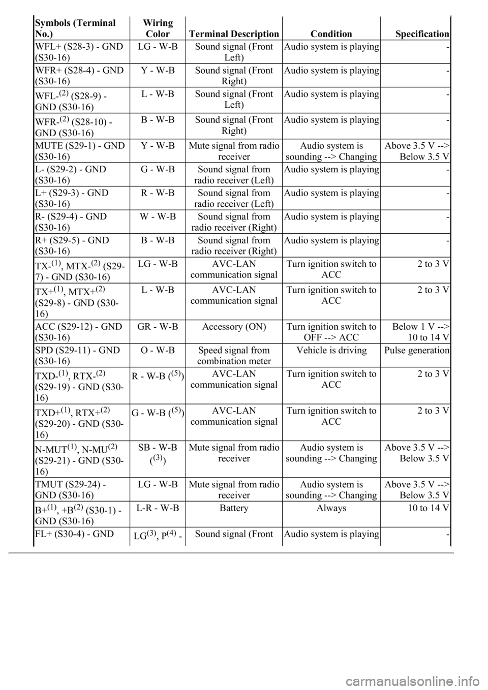
Symbols (Terminal
No.)Wiring
Color
Terminal DescriptionConditionSpecification
WFL+ (S28-3) - GND
(S30-16)LG - W-BSound signal (Front
Left)Audio system is playing-
WFR+ (S28-4) - GND
(S30-16)Y - W-BSound signal (Front
Right)Audio system is playing-
WFL-(2) (S28-9) -
GND (S30-16)L - W-BSound signal (Front
Left)Audio system is playing-
WFR-(2) (S28-10) -
GND (S30-16)B - W-BSound signal (Front
Right)Audio system is playing-
MUTE (S29-1) - GND
(S30-16)Y - W-BMute signal from radio
receiverAudio system is
sounding --> ChangingAbove 3.5 V -->
Below 3.5 V
L- (S29-2) - GND
(S30-16)G - W-BSound signal from
radio receiver (Left)Audio system is playing-
L+ (S29-3) - GND
(S30-16)R - W-BSound signal from
radio receiver (Left)Audio system is playing-
R- (S29-4) - GND
(S30-16)W - W-BSound signal from
radio receiver (Right)Audio system is playing-
R+ (S29-5) - GND
(S30-16)B - W-BSound signal from
radio receiver (Right)Audio system is playing-
TX-(1), MTX-(2) (S29-
7) - GND (S30-16)LG - W-BAVC-LAN
communication signalTurn ignition switch to
ACC2 to 3 V
TX+(1), MTX+(2)
(S29-8) - GND (S30-
16)L - W-BAVC-LAN
communication signalTurn ignition switch to
ACC2 to 3 V
ACC (S29-12) - GND
(S30-16)GR - W-BAccessory (ON)Turn ignition switch to
OFF --> ACCBelow 1 V -->
10 to 14 V
SPD (S29-11) - GND
(S30-16)O - W-BSpeed signal from
combination meterVehicle is drivingPulse generation
TXD-(1), RTX-(2)
(S29-19) - GND (S30-
16)R - W-B ((5))AVC-LAN
communication signalTurn ignition switch to
ACC2 to 3 V
TXD+(1), RTX+(2)
(S29-20) - GND (S30-
16)G - W-B ((5))AVC-LAN
communication signalTurn ignition switch to
ACC2 to 3 V
N-MUT(1), N-MU(2)
(S29-21) - GND (S30-
16)SB - W-B
(
(3))
Mute signal from radio
receiverAudio system is
sounding --> ChangingAbove 3.5 V -->
Below 3.5 V
TMUT (S29-24) -
GND (S30-16)LG - W-BMute signal from radio
receiverAudio system is
sounding --> ChangingAbove 3.5 V -->
Below 3.5 V
B+(1), +B(2) (S30-1) -
GND (S30-16)L-R - W-BBatteryAlways10 to 14 V
FL+ (S30-4) - GND LG(3), P(4) - Sound signal (Front Audio system is playing-