2003 LEXUS LS430 heater
[x] Cancel search: heaterPage 210 of 4500

Fig. 6: Air Conditioning System Diagram (2 Of 2)
Courtesy of TOYOTA MOTOR SALES, U.S.A., INC.
1.GENERAL
a. The air conditioning system has the following features:
In compliance with the temperature set at the temperature control switch, the neural network
control calculates the outlet temperature based on the input signals from various sensors. In
addition, corrections in accordance with the signals from the evaporative temperature sensor
and the water temperature sensor are added to control the outlet air temperature.
Controls the front and rear blower motors in accordance with the airflow volume that has
been calculated by the neural network control based on the input signals from various
sensors.
Automatically switches the outlets in accordance with the outlet mode ratio that has been
calculated by the neural network control based on the input signals from various sensors.
Automatically controls the air inlet control damper in accordance with the airflow volume
that has been calculated by the neural network control.
Turns the compressor on/off and controls the discharge capacity based on the signals from
various sensors.
Based on the signals from the ambient temperature sensor, this control calculates the outside
temperature, which is then corrected in the air conditioner ECU, and shown in the multi-
information display in the combination meter.
Switched the rear defogger and outside rear view mirror heaters on for 15 minutes when the
rear defogger switch is switched on. Switched them off if the switch is pressed while they are
operating.
Controls the orientation and the angle of the front center register based on the input signals
from various sensors and on the outlet mode.
Determines whether the clean air filter (for the front A/C) is clogged by monitoring the air
inlets, and airflow volume.
The A/C amplifier automatically controls the air inlets based on the signals from the smog
ventilation sensor.
Improves the air quality by linking the air inlet control damper and the blower motor (for the
rear A/C and air purifier), based on the signals from the exhaust gas sensor and the smoke
sensor.
Checks the sensors in accordance with operation of the air conditioner switches.
2.MODEL POSITION AND DAMPER OPERATION
Page 373 of 4500
Amplifier)
Courtesy of TOYOTA MOTOR SALES, U.S.A., INC.
NG: REPAIR OR REPLACE HARNESS OR CONNECTOR
OK: REPLACE AIR CONDITIONING AMPLIFIER (SEE REPLACEMENT
)
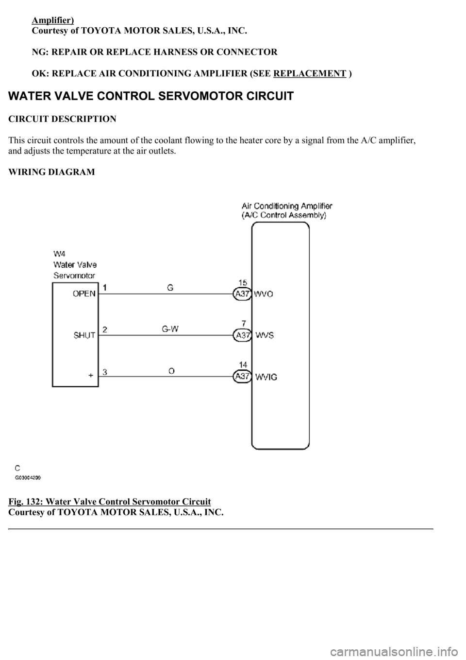
CIRCUIT DESCRIPTION
This circuit controls the amount of the coolant flowing to the heater core by a signal from the A/C amplifier,
and adjusts the temperature at the air outlets.
WIRING DIAGRAM
Fig. 132: Water Valve Control Servomotor Circuit
Courtesy of TOYOTA MOTOR SALES, U.S.A., INC.
Page 414 of 4500
b. Turn the radio and receiver assy on.
c. Set the radio channels and register them.
d. Turn the ignition switch off.
e. Turn the ignition switch to the ON position.
f. Turn the radio and receiver assy on.
g. Check if the registered memory is deleted or not.
OK:
The registered memory is not deleted.
NG: REPAIR OR REPLACE HARNESS OR CONNECTOR (DRIVER SIDE J/B - BATTERY)
OK: Go to next step
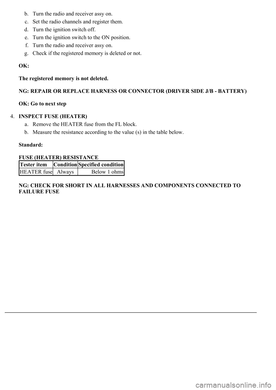
4.INSPECT FUSE (HEATER)
a. Remove the HEATER fuse from the FL block.
b. Measure the resistance according to the value (s) in the table below.
Standard:
FUSE (HEATER) RESISTANCE
NG: CHECK FOR SHORT IN ALL HARNESSES AND COMPONENTS CONNECTED TO
FAILURE FUSE
Tester itemConditionSpecified condition
HEATER fuseAlwaysBelow 1 ohms
Page 415 of 4500
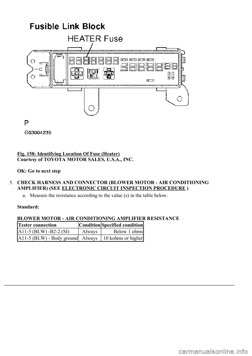
Fig. 158: Identifying Location Of Fuse (Heater)
Courtesy of TOYOTA MOTOR SALES, U.S.A., INC.
OK: Go to next step
5.CHECK HARNESS AND CONNECTOR (BLOWER MOTOR - AIR CONDITIONING
AMPLIFIER) (SEE ELECTRONIC CIRCUIT INSPECTION PROCEDURE
)
a. Measure the resistance according to the value (s) in the table below.
Standard:
BLOWER MOTOR - AIR CONDITIONING AMPLIFIER RESISTANCE
Tester connectionConditionSpecified condition
A11-5 (BLW) -B2-2 (SI)AlwaysBelow 1 ohms
A11-5 (BLW) - Body groundAlways10 kohms or higher
Page 749 of 4500

NG: REPLACE THE CD
OK: Go to next step
3.CHECK RADIO RECEIVER ASSY
a. Insert another CD and check if it is ejected.
OK: The disc is ejected.
NG: REPLACE RADIO RECEIVER ASSY (SEE REPLACEMENT
)
OK: NORMAL OPERATION
INSPECTION PROCEDURE
1.CHECK SPEAKERS
a. Check the speaker unit installed condition.
1. Check that each speaker is securely installed.
OK: The problem goes away.
HINT:
The radio has a noise prevention function to reduce noise when listening to the radio. If a loud noise
occurs, check whether the ground at the antenna mounting base and the noise prevention unit are installed
and wired correctly.
NOISE CONDITION CHART
Noise ConditionsNoise Source
Depressing the accelerator pedal makes the noise louder. However, the noise
stops immediately when the engine is stopped.Alternator
Noise occurs while the A/C or heater is in operation.Blower motor
Noise can be heard during sudden acceleration on an unpaved road, or after the
ignition switch is turned ON.Fuel pump
Noise can be heard when the horn is pressed and released, or held down
continuously.Horn
<00340058004c00480057000300510052004c0056004800030046004400510003004500480003004b00480044005500470003005a004b004c004f004800030057004b0048000300480051004a004c0051004800030055005800510056000f00030045005800
570003005600570052005300560003005a004b004800510003[the engine is
stopped.Ignition
Noise can be heard when the turn signal blinks.Flasher
Noise can be heard while window washer is in operation.Washer
Noise can be heard while the engine is running and continues after it is stopped.Water temperature
sensor
Noise can be heard while the wiper system is in operation.Wiper
Page 1596 of 4500
HINT:
*1: For vehicles with a rear seat heater system
*2: For vehicles with a rear seat climate control system
If the result is not as specified, there may be a malfunction on the wire harness side.
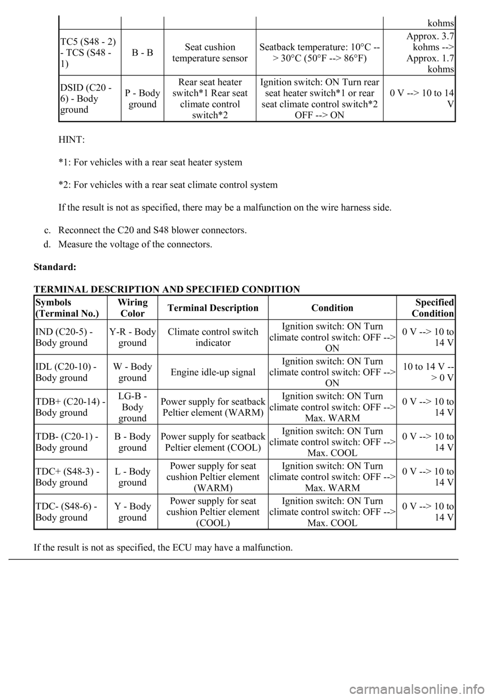
c. Reconnect the C20 and S48 blower connectors.
d. Measure the voltage of the connectors.
Standard:
TERMINAL DESCRIPTION AND SPECIFIED CONDITION
If the result is not as specified, the ECU ma
y have a malfunction.
kohms
TC5 (S48 - 2)
- TCS (S48 -
1)
B - BSeat cushion
temperature sensorSeatback temperature: 10°C --
> 30°C (50°F --> 86°F)
Approx. 3.7
kohms -->
Approx. 1.7
kohms
DSID (C20 -
6) - Body
groundP - Body
ground
Rear seat heater
switch*1 Rear seat
climate control
switch*2Ignition switch: ON Turn rear
seat heater switch*1 or rear
seat climate control switch*2
OFF --> ON
0 V --> 10 to 14
V
Symbols
(Terminal No.)Wiring
ColorTerminal DescriptionConditionSpecified
Condition
IND (C20-5) -
Body groundY-R - Body
groundClimate control switch
indicatorIgnition switch: ON Turn
climate control switch: OFF -->
ON0 V --> 10 to
14 V
IDL (C20-10) -
Body groundW - Body
groundEngine idle-up signal
Ignition switch: ON Turn
climate control switch: OFF -->
ON10 to 14 V --
> 0 V
TDB+ (C20-14) -
Body groundLG-B -
Body
groundPower supply for seatback
Peltier element (WARM)Ignition switch: ON Turn
climate control switch: OFF -->
Max. WARM0 V --> 10 to
14 V
TDB- (C20-1) -
Body groundB - Body
groundPower supply for seatback
Peltier element (COOL)Ignition switch: ON Turn
climate control switch: OFF -->
Max. COOL0 V --> 10 to
14 V
TDC+ (S48-3) -
Body groundL - Body
groundPower supply for seat
cushion Peltier element
(WARM)Ignition switch: ON Turn
climate control switch: OFF -->
Max. WARM0 V --> 10 to
14 V
TDC- (S48-6) -
Body groundY - Body
groundPower supply for seat
cushion Peltier element
(COOL)Ignition switch: ON Turn
climate control switch: OFF -->
Max. COOL0 V --> 10 to
14 V
Page 1598 of 4500
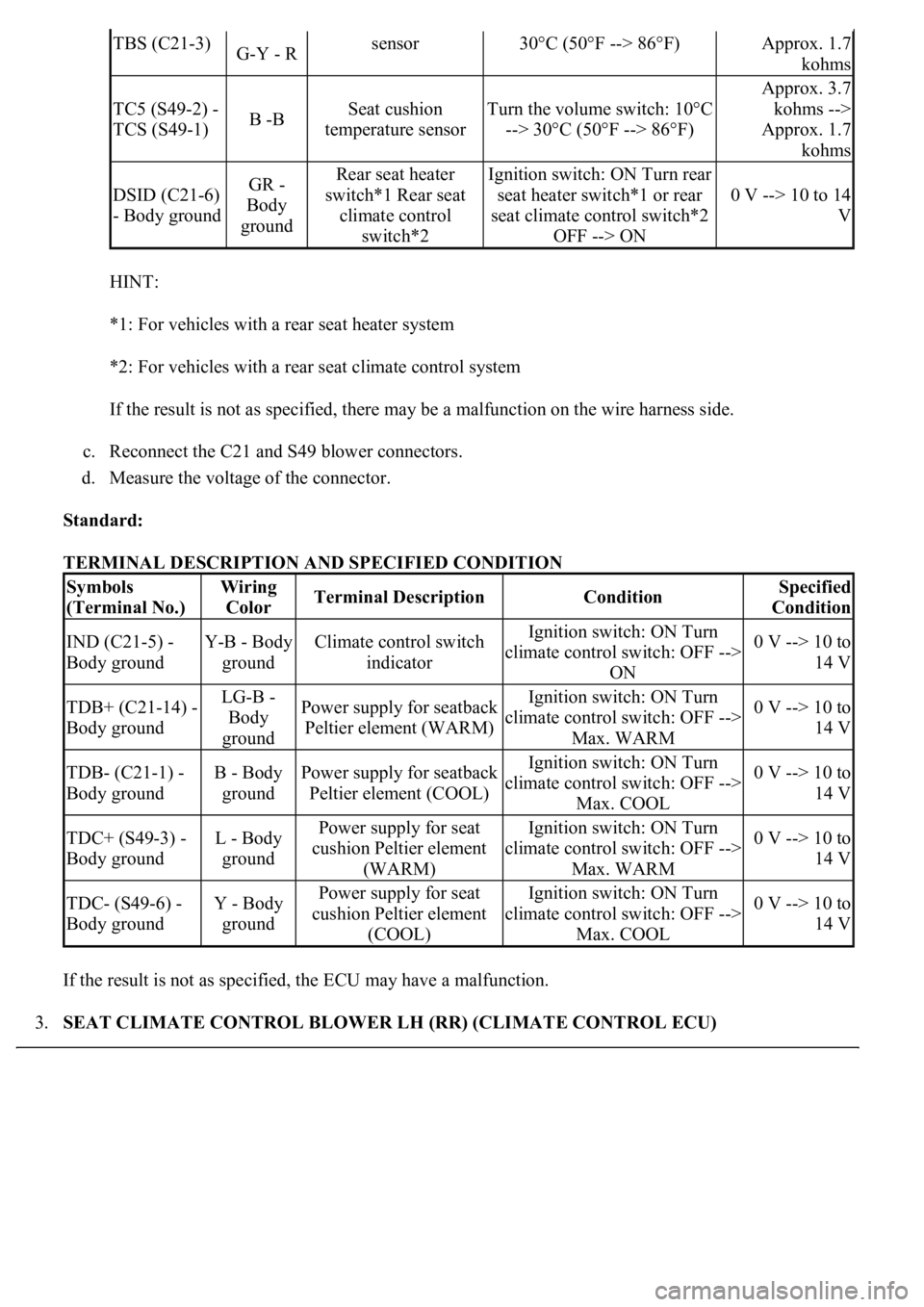
HINT:
*1: For vehicles with a rear seat heater system
*2: For vehicles with a rear seat climate control system
If the result is not as specified, there may be a malfunction on the wire harness side.
c. Reconnect the C21 and S49 blower connectors.
d. Measure the voltage of the connector.
Standard:
TERMINAL DESCRIPTION AND SPECIFIED CONDITION
If the result is not as specified, the ECU may have a malfunction.
3.SEAT CLIMATE CONTROL BLOWER LH (RR) (CLIMATE CONTROL ECU)
TBS (C21-3)G-Y - Rsensor30°C (50°F --> 86°F)Approx. 1.7
kohms
TC5 (S49-2) -
TCS (S49-1)B -BSeat cushion
temperature sensorTurn the volume switch: 10°C
--> 30°C (50°F --> 86°F)
Approx. 3.7
kohms -->
Approx. 1.7
kohms
DSID (C21-6)
- Body groundGR -
Body
groundRear seat heater
switch*1 Rear seat
climate control
switch*2Ignition switch: ON Turn rear
seat heater switch*1 or rear
seat climate control switch*2
OFF --> ON
0 V --> 10 to 14
V
Symbols
(Terminal No.)Wiring
ColorTerminal DescriptionConditionSpecified
Condition
IND (C21-5) -
Body groundY-B - Body
groundClimate control switch
indicatorIgnition switch: ON Turn
climate control switch: OFF -->
ON0 V --> 10 to
14 V
TDB+ (C21-14) -
Body groundLG-B -
Body
groundPower supply for seatback
Peltier element (WARM)Ignition switch: ON Turn
climate control switch: OFF -->
Max. WARM0 V --> 10 to
14 V
TDB- (C21-1) -
Body groundB - Body
groundPower supply for seatback
Peltier element (COOL)Ignition switch: ON Turn
climate control switch: OFF -->
Max. COOL0 V --> 10 to
14 V
TDC+ (S49-3) -
Body groundL - Body
groundPower supply for seat
cushion Peltier element
(WARM)Ignition switch: ON Turn
climate control switch: OFF -->
Max. WARM0 V --> 10 to
14 V
TDC- (S49-6) -
Body groundY - Body
groundPower supply for seat
cushion Peltier element
(COOL)Ignition switch: ON Turn
climate control switch: OFF -->
Max. COOL0 V --> 10 to
14 V
Page 1599 of 4500
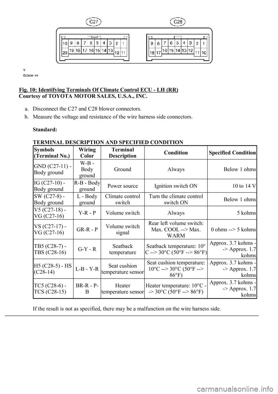
Fig. 10: Identifying Terminals Of Climate Control ECU - LH (RR)
Courtesy of TOYOTA MOTOR SALES, U.S.A., INC.
a. Disconnect the C27 and C28 blower connectors.
b. Measure the voltage and resistance of the wire harness side connectors.
Standard:
TERMINAL DESCRIPTION AND SPECIFIED CONDITION
If the result is not as specified, there ma
y be a malfunction on the wire harness side.
Symbols
(Terminal No.)Wiring
ColorTerminal
DescriptionConditionSpecified Condition
GND (C27-11) -
Body groundW-B -
Body
ground
GroundAlwaysBelow 1 ohms
IG (C27-10) -
Body groundR-B - Body
groundPower sourceIgnition switch ON10 to 14 V
SW (C27-8) -
Body groundL - Body
groundClimate control
switchTurn the climate control
switch ONBelow 1 ohms
V5 (C27-18) -
VG (C27-16)Y-R - PVolume switchAlways5 kohms
VS (C27-17) -
VG (C27-16)GR-R - PVolume switch
signalRear left volume switch:
Max. COOL --> Max.
WARM
0 ohms --> 5 kohms
TB5 (C28-7) -
TBS (C28-16)G-Y - RSeatback
temperatureSeatback temperature: 10°
C --> 30°C (50°F --> 86°F)Approx. 3.7 kohms -
-> Approx. 1.7
kohms
H5 (C28-5) - HS
(C28-14)L-B - Y-RSeat cushion
temperature sensorSeat cushion temperature:
10°C --> 30°C (50°F -->
86°F)Approx. 3.7 kohms -
-> Approx. 1.7
kohms
TC5 (C28-6) -
TCS (C28-15)BR-R - P-
BHeater
temperature sensorHeater temperature: 10°C -
-> 30°C (50°F --> 86°F)Approx. 3.7 kohms -
-> Approx. 1.7
kohms