Page 5 of 4500
Fig. 2: ABS With EBD & BA & TRAC & VSC System Diagram (1 Of 2)
Courtesy of TOYOTA MOTOR SALES, U.S.A., INC.
Page 6 of 4500

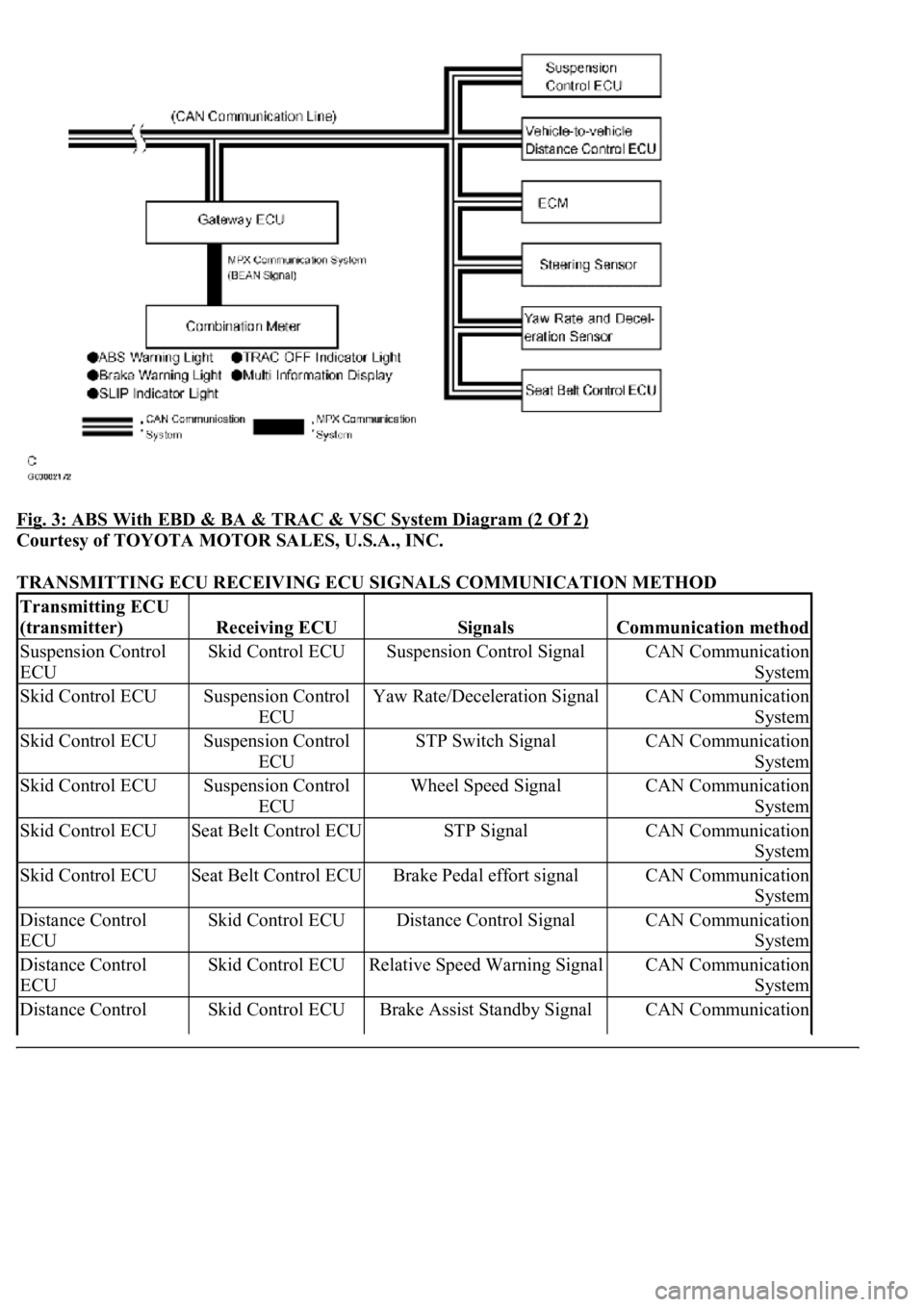
Fig. 3: ABS With EBD & BA & TRAC & VSC System Diagram (2 Of 2)
Courtesy of TOYOTA MOTOR SALES, U.S.A., INC.
TRANSMITTING ECU RECEIVING ECU SIGNALS COMMUNICATION METHOD
Transmitting ECU
(transmitter)
Receiving ECUSignalsCommunication method
Suspension Control
ECUSkid Control ECUSuspension Control SignalCAN Communication
System
Skid Control ECUSuspension Control
ECUYaw Rate/Deceleration SignalCAN Communication
System
Skid Control ECUSuspension Control
ECUSTP Switch SignalCAN Communication
System
Skid Control ECUSuspension Control
ECUWheel Speed SignalCAN Communication
System
Skid Control ECUSeat Belt Control ECUSTP SignalCAN Communication
System
Skid Control ECUSeat Belt Control ECUBrake Pedal effort signalCAN Communication
System
Distance Control
ECUSkid Control ECUDistance Control SignalCAN Communication
System
Distance Control
ECUSkid Control ECURelative Speed Warning SignalCAN Communication
System
Distance Control Skid Control ECUBrake Assist Standby SignalCAN Communication
Page 62 of 4500
Fig. 45: DTC C0200/31 And DTC C0205/32 Detecting Condition And Trouble Area
Courtesy of TOYOTA MOTOR SALES, U.S.A., INC.
HINT:
DTC C0200/31 is for the right front speed sensor.
DTC C0205/32 is for the left front speed sensor.
WIRING DIAGRAM
Fig. 46: Right Front Speed Sensor Wiring Diagram
Courtesy of TOYOTA MOTOR SALES, U.S.A., INC.
INSPECTION PROCEDURE
1.CHECK HARNESS AND CONNECTOR (MOMENTARY INTERRUPTION)
a. Using the hand-held tester, check for any momentary interruption in the wire harness and connector
corresponding to a DTC (see CHECK FOR INTERMITTENT PROBLEMS
).
Page 74 of 4500
Refer to DTC C0200/31 RIGHT FRONT SPEED SENSORor DTC C0205/32 LEFT FRONT SPEED
SENSOR .
Fig. 53: DTC C0210/33 And DTC C0215/34 Detecting Condition And Trouble Area
Courtesy of TOYOTA MOTOR SALES, U.S.A., INC.
HINT:
DTC C0210/33 is for the right rear speed sensor.
DTC C0215/34 is for the left rear speed sensor.
WIRING DIAGRAM
Fig. 54: Rear Speed Sensor Wiring Diagram
Courtesy of TOYOTA MOTOR SALES, U.S.A., INC.
INSPECTION PROCEDURE
1.CHECK HARNESS AND CONNECTOR
a. Usin
g the hand-held tester, check for any momentary interruption in the wire harness and connector
Page 84 of 4500
Fig. 60: DTC C0226/21 And DTC C1225/25 Detecting Condition And Trouble Area
Courtesy of TOYOTA MOTOR SALES, U.S.A., INC.
WIRING DIAGRAM
Page 85 of 4500
Fig. 61: SFL Solenoid Wiring Diagram
Courtesy of TOYOTA MOTOR SALES, U.S.A., INC.
INSPECTION PROCEDURE
1.RECONFIRM DTC
HINT:
This code is detected when a problem is determined in the brake actuator assy.
The ABS solenoid circuit is in the brake actuator assy. Therefore, solenoid circuit inspection relay unit
inspection cannot be performed. Be sure to check if the DTC code is output before replacing the brake
actuator assy.
a. Clear the DTC (see DTC CHECK/CLEAR
).
b. Start the engine.
c. Drive the vehicle at the speed of 4 mph (6 km/h) or more.
d. Check that the same DTC is recorded.
Page 87 of 4500
Fig. 62: DTC C0273/13 And DTC C0274/14 Detecting Condition And Trouble Area
Courtesy of TOYOTA MOTOR SALES, U.S.A., INC.
WIRING DIAGRAM
Page 88 of 4500
Fig. 63: ABS Motor Relay Wiring Diagram
Courtesy of TOYOTA MOTOR SALES, U.S.A., INC.
INSPECTION PROCEDURE
1.PERFORM ACTIVE TEST BY HAND-HELD TESTER (ABS MOTOR RELAY OPERATION)
a. Connect the hand-held tester to the DLC3.
b. Start the engine.
c. Select the ACTIVE TEST mode on the hand-held tester.
d. Check the operation sound of the ABS motor individually when operating it with the hand-held
tester.