Page 154 of 4500

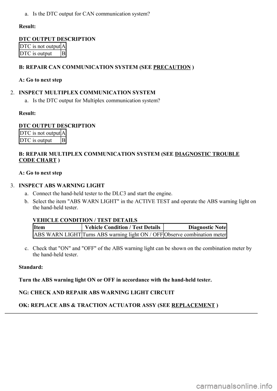
a. Is the DTC output for CAN communication system?
Result:
DTC OUTPUT DESCRIPTION
B: REPAIR CAN COMMUNICATION SYSTEM (SEE PRECAUTION
)
A: Go to next step
2.INSPECT MULTIPLEX COMMUNICATION SYSTEM
a. Is the DTC output for Multiplex communication system?
Result:
DTC OUTPUT DESCRIPTION
B: REPAIR MULTIPLEX COMMUNICATION SYSTEM (SEE DIAGNOSTIC TROUBLE
CODE CHART )
A: Go to next step
3.INSPECT ABS WARNING LIGHT
a. Connect the hand-held tester to the DLC3 and start the engine.
b. Select the item "ABS WARN LIGHT" in the ACTIVE TEST and operate the ABS warning light on
the hand-held tester.
VEHICLE CONDITION / TEST DETAILS
c. Check that "ON" and "OFF" of the ABS warning light can be shown on the combination meter by
the hand-held tester.
Standard:
Turn the ABS warning light ON or OFF in accordance with the hand-held tester.
NG: CHECK AND REPAIR ABS WARNING LIGHT CIRCUIT
OK: REPLACE ABS & TRACTION ACTUATOR ASSY (SEE REPLACEMENT
)
DTC is not outputA
DTC is outputB
DTC is not outputA
DTC is outputB
ItemVehicle Condition / Test DetailsDiagnostic Note
ABS WARN LIGHTTurns ABS warning light ON / OFFObserve combination meter
Page 161 of 4500

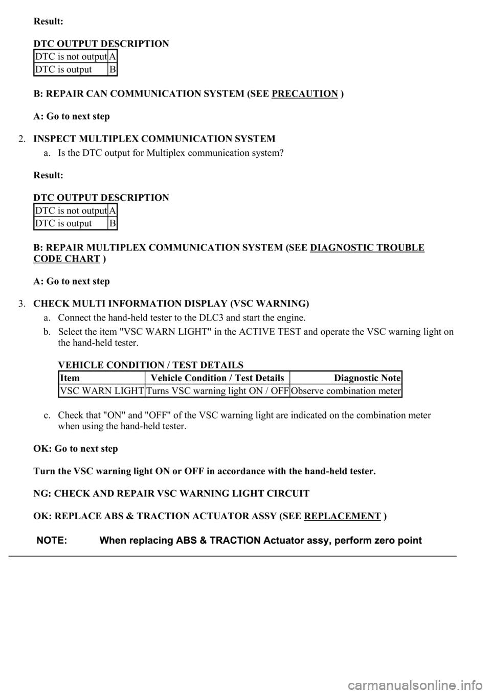
Result:
DTC OUTPUT DESCRIPTION
B: REPAIR CAN COMMUNICATION SYSTEM (SEE PRECAUTION
)
A: Go to next step
2.INSPECT MULTIPLEX COMMUNICATION SYSTEM
a. Is the DTC output for Multiplex communication system?
Result:
DTC OUTPUT DESCRIPTION
B: REPAIR MULTIPLEX COMMUNICATION SYSTEM (SEE DIAGNOSTIC TROUBLE
CODE CHART )
A: Go to next step
3.CHECK MULTI INFORMATION DISPLAY (VSC WARNING)
a. Connect the hand-held tester to the DLC3 and start the engine.
b. Select the item "VSC WARN LIGHT" in the ACTIVE TEST and operate the VSC warning light on
the hand-held tester.
VEHICLE CONDITION / TEST DETAILS
c. Check that "ON" and "OFF" of the VSC warning light are indicated on the combination meter
when using the hand-held tester.
OK: Go to next step
Turn the VSC warning light ON or OFF in accordance with the hand-held tester.
NG: CHECK AND REPAIR VSC WARNING LIGHT CIRCUIT
OK: REPLACE ABS & TRACTION ACTUATOR ASSY (SEE REPLACEMENT
)
DTC is not outputA
DTC is outputB
DTC is not outputA
DTC is outputB
ItemVehicle Condition / Test DetailsDiagnostic Note
VSC WARN LIGHTTurns VSC warning light ON / OFFObserve combination meter
Page 183 of 4500

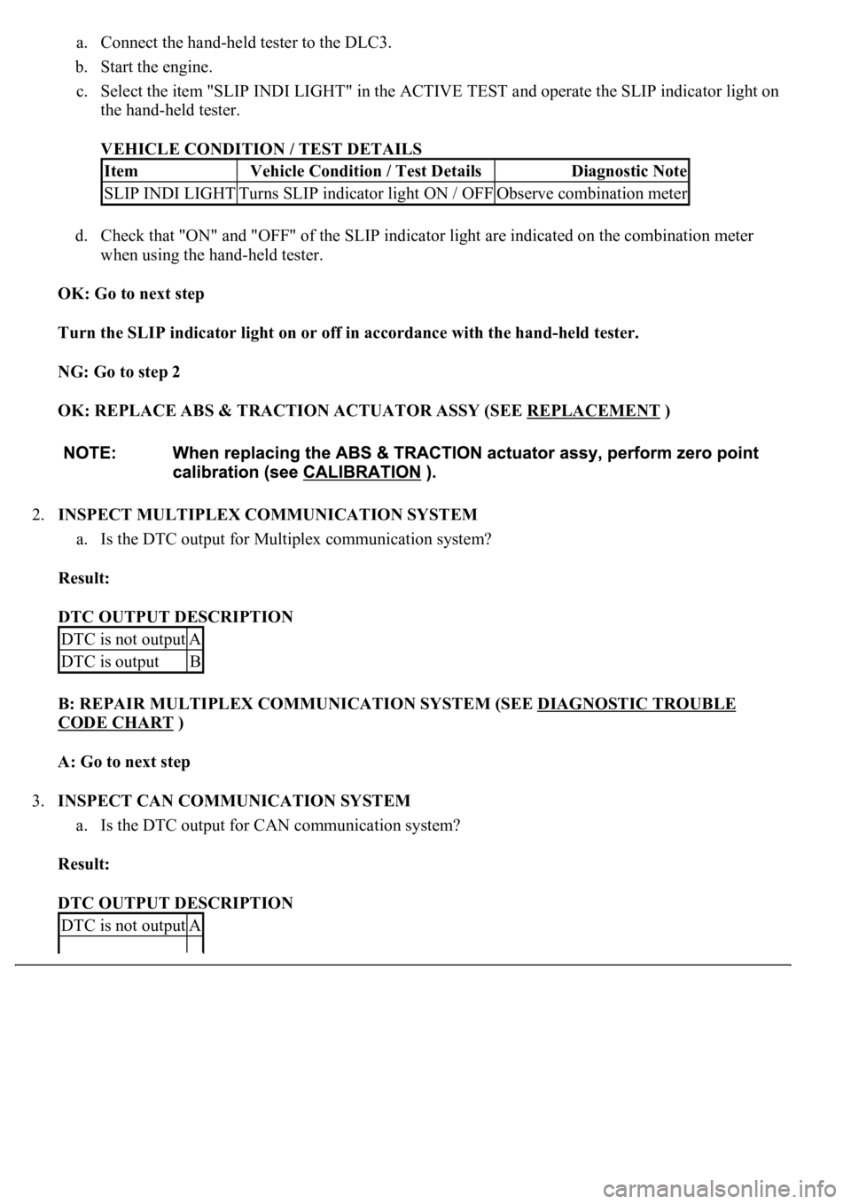
a. Connect the hand-held tester to the DLC3.
b. Start the engine.
c. Select the item "SLIP INDI LIGHT" in the ACTIVE TEST and operate the SLIP indicator light on
the hand-held tester.
VEHICLE CONDITION / TEST DETAILS
d. Check that "ON" and "OFF" of the SLIP indicator light are indicated on the combination meter
when using the hand-held tester.
OK: Go to next step
Turn the SLIP indicator light on or off in accordance with the hand-held tester.
NG: Go to step 2
OK: REPLACE ABS & TRACTION ACTUATOR ASSY (SEE REPLACEMENT
)
2.INSPECT MULTIPLEX COMMUNICATION SYSTEM
a. Is the DTC output for Multiplex communication system?
Result:
DTC OUTPUT DESCRIPTION
B: REPAIR MULTIPLEX COMMUNICATION SYSTEM (SEE DIAGNOSTIC TROUBLE
CODE CHART )
A: Go to next step
3.INSPECT CAN COMMUNICATION SYSTEM
a. Is the DTC output for CAN communication system?
Result:
DTC OUTPUT DESCRIPTION
ItemVehicle Condition / Test DetailsDiagnostic Note
SLIP INDI LIGHTTurns SLIP indicator light ON / OFFObserve combination meter
DTC is not outputA
DTC is outputB
DTC is not outputA
Page 1940 of 4500
![LEXUS LS430 2003 Factory Repair Manual Fig. 31: [Disconnecting ECM Connector]
Courtesy of TOYOTA MOTOR SALES, U.S.A., INC.
NG: REPAIR OR REPLACE HARNESS OR CONNECTOR
OK: REPLACE ECM (SEE REPLACEMENT
)
CIRCUIT DESCRIPTION
The ECM det LEXUS LS430 2003 Factory Repair Manual Fig. 31: [Disconnecting ECM Connector]
Courtesy of TOYOTA MOTOR SALES, U.S.A., INC.
NG: REPAIR OR REPLACE HARNESS OR CONNECTOR
OK: REPLACE ECM (SEE REPLACEMENT
)
CIRCUIT DESCRIPTION
The ECM det](/manual-img/36/57050/w960_57050-1939.png)
Fig. 31: [Disconnecting ECM Connector]
Courtesy of TOYOTA MOTOR SALES, U.S.A., INC.
NG: REPAIR OR REPLACE HARNESS OR CONNECTOR
OK: REPLACE ECM (SEE REPLACEMENT
)
CIRCUIT DESCRIPTION
The ECM detects a cruise control switch signal and sends it to the combination meter via CAN and
BEAN. Then the CRUISE main indicator light comes on.
The CRUISE main indicator light circuit uses CAN and BEAN for communication. If there are any
malfunctions in this circuit, check for DTCs in the CAN communication system and multiplex
communication system.
INSPECTION PROCEDURE
1.PERFORM ACTIVE TEST BY HAND-HELD TESTER
a. Connect the hand-held tester to the DLC3.
b. Check the CRUISE main indicator light by using ACTIVE TEST.
ACTIVE TEST DETAIL (COMBINATION METER ASSY)
OK: Indicator light comes on/goes off.
NG: GO TO COMBINATION METER SYSTEM (SEE HOW TO PROCEED WITH
TROUBLESHOOTING )
OK: Go to next step
2.READ VALUE ON HAND-HELD TESTER
a. Connect the hand-held tester to the DLC3.
b. Turn the ignition switch to the ON position and turn the hand-held tester main switch on.
c. Select the item below in the "DATA LIST", and read the display on the hand-held tester.
DATA LIST (CC (ECM))
ItemVehicle Condition / Test DetailsDiagnostic Note
CRUISE INDIC"CRUISE" indicator is ON / OFF-
ItemMeasurement Item / Display
(Range)Normal ConditionDiagnostic
Note
CCS INDICATOR
MCruise indicator signal (Main
CPU) /ON or OFFON: "CCS READY" ON OFF:
"CCS READY" OFF-