Page 1781 of 4500

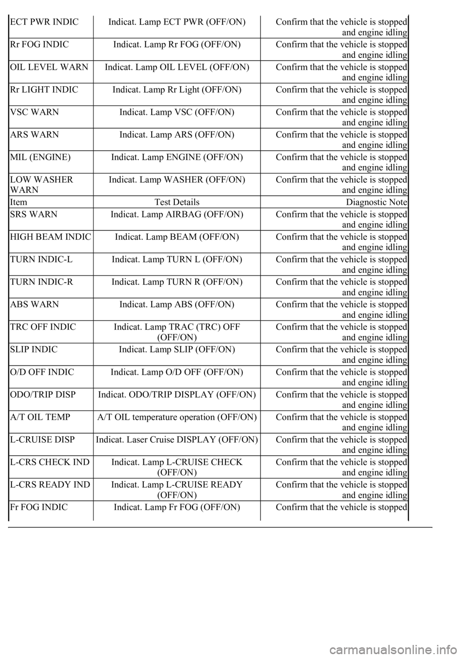
ECT PWR INDICIndicat. Lamp ECT PWR (OFF/ON)Confirm that the vehicle is stopped
and engine idling
Rr FOG INDICIndicat. Lamp Rr FOG (OFF/ON)Confirm that the vehicle is stopped
and engine idling
OIL LEVEL WARNIndicat. Lamp OIL LEVEL (OFF/ON)Confirm that the vehicle is stopped
and engine idling
Rr LIGHT INDICIndicat. Lamp Rr Light (OFF/ON)Confirm that the vehicle is stopped
and engine idling
VSC WARNIndicat. Lamp VSC (OFF/ON)Confirm that the vehicle is stopped
and engine idling
ARS WARNIndicat. Lamp ARS (OFF/ON)Confirm that the vehicle is stopped
and engine idling
MIL (ENGINE)Indicat. Lamp ENGINE (OFF/ON)Confirm that the vehicle is stopped
and engine idling
LOW WASHER
WARNIndicat. Lamp WASHER (OFF/ON)Confirm that the vehicle is stopped
and engine idling
ItemTest DetailsDiagnostic Note
SRS WARNIndicat. Lamp AIRBAG (OFF/ON)Confirm that the vehicle is stopped
and engine idling
HIGH BEAM INDICIndicat. Lamp BEAM (OFF/ON)Confirm that the vehicle is stopped
and engine idling
TURN INDIC-LIndicat. Lamp TURN L (OFF/ON)Confirm that the vehicle is stopped
and engine idling
TURN INDIC-RIndicat. Lamp TURN R (OFF/ON)Confirm that the vehicle is stopped
and engine idling
ABS WARNIndicat. Lamp ABS (OFF/ON)Confirm that the vehicle is stopped
and engine idling
TRC OFF INDICIndicat. Lamp TRAC (TRC) OFF
(OFF/ON)Confirm that the vehicle is stopped
and engine idling
SLIP INDICIndicat. Lamp SLIP (OFF/ON)Confirm that the vehicle is stopped
and engine idling
O/D OFF INDICIndicat. Lamp O/D OFF (OFF/ON)Confirm that the vehicle is stopped
and engine idling
ODO/TRIP DISPIndicat. ODO/TRIP DISPLAY (OFF/ON)Confirm that the vehicle is stopped
and engine idling
A/T OIL TEMPA/T OIL temperature operation (OFF/ON)Confirm that the vehicle is stopped
and engine idling
L-CRUISE DISPIndicat. Laser Cruise DISPLAY (OFF/ON)Confirm that the vehicle is stopped
and engine idling
L-CRS CHECK INDIndicat. Lamp L-CRUISE CHECK
(OFF/ON)Confirm that the vehicle is stopped
and engine idling
L-CRS READY INDIndicat. Lamp L-CRUISE READY
(OFF/ON)Confirm that the vehicle is stopped
and engine idling
Fr FOG INDICIndicat. Lamp Fr FOG (OFF/ON)Confirm that the vehicle is stopped
Page 1956 of 4500
c. Adjust the laser beam axis
1. Turn the ignition switch to the ON position.
2. Push the cruise control main switch ON-OFF button on.
3. Connect the hand-held tester to the DLC3, and turn the power ON.
Fig. 9: Connecting Hand
-Held Tester To DLC3
Courtesy of TOYOTA MOTOR SALES, U.S.A., INC.
4. Operate by following the screen menu and select "BEAM AXIS ADJUST" of the Laser Cruise
Control, then press the "ENTER" key.
HINT:
Pressing the "ENTER" key will make the ECM transfer to BEAM AXIS ADJUSTMENT
MODE.
When the ECM transfers to BEAM AXIS ADJUSTMENT MODE, the buzzer sounds for 1
second.
Page 1962 of 4500
Fig. 15: Confirming Current Value Of Laser Beam
Courtesy of TOYOTA MOTOR SALES, U.S.A., INC.
13. Press the "ENTER" key.
HINT:
*1: Either UPPER or LOWER is indicated.
*2: Either LEFT or RIGHT is indicated.
*3: Values between 0.0 and 6.3 are indicated.
The direction and angle that actually deviate from the spec are displayed in the multi-information
display on the combination meter when starting the optical axis adjustment mode with the hand-
held tester.
14. Move the reflector either to the right or left by 100 mm (3.937 in.) and check that the value
changes.
Page 1963 of 4500
15. Return the reflector to the original position and read the current angle.
DIVERGENCE OF BEAM AXIS TABLE
HINT:
When the values displayed on the screen are normal, the values are within the above range. If the
value is out of range, check the installation condition of the bumper reinforcement, etc.
16. Turn the headlamp dimmer switch to the TAIL position.
17. Press the "ENTER" key.
Fig. 16: Identifying "ENTER" Key
UPPER/LOWER SIDE-2° TO +2°
RIGHT/LEFT SIDE-4° TO +4°
Page 1974 of 4500
Fig. 27: Measuring To Left And Placing Reflector
Courtesy of TOYOTA MOTOR SALES, U.S.A., INC.
f. Adjust the radar beam axis
1. Turn the ignition switch to the ON position.
2. Push the cruise control main switch ON-OFF button on.
3. Connect the hand-held tester to the DLC3, and turn the power ON.
Fig. 28: Connecting Hand
-Held Tester To DLC3
Courtesy of TOYOTA MOTOR SALES, U.S.A., INC.
4. Operate by following the screen menu and select "BEAM AXIS ADJUST" of the Radar
Cruise Control, then press the "ENTER" key.
HINT:
Pressing the "ENTER" key will make the ECM transfer to BEAM AXIS
ADJUSTMENT MODE.
When the ECM transfers to BEAM AXIS ADJUSTMENT MODE, the buzzer sounds
for 1 second.
Page 2438 of 4500

front with the vehicle-to-vehicle distance control mode does not increase the actual vehicle
speed, but changes only the set vehicle speed.
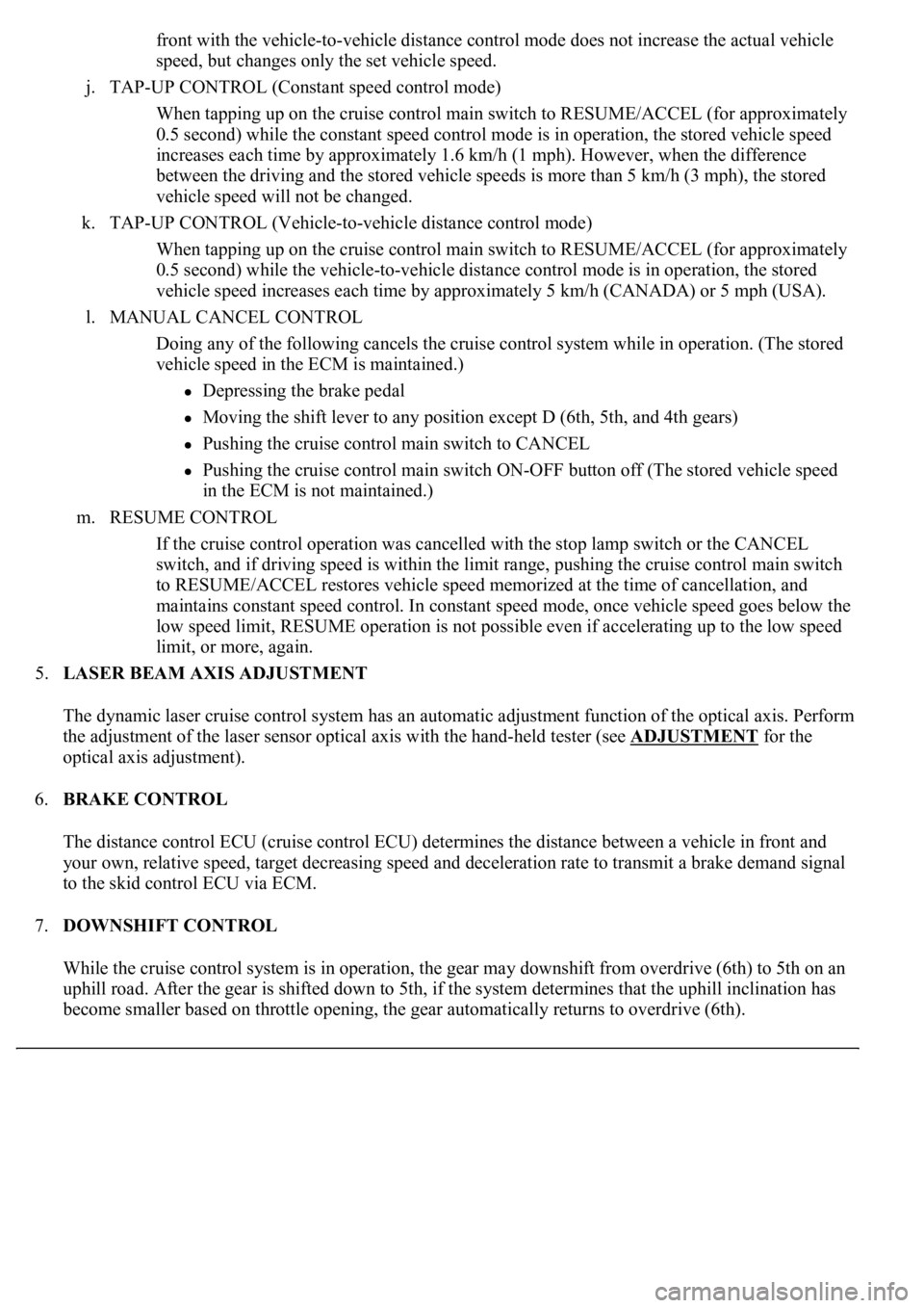
j. TAP-UP CONTROL (Constant speed control mode)
When tapping up on the cruise control main switch to RESUME/ACCEL (for approximately
0.5 second) while the constant speed control mode is in operation, the stored vehicle speed
increases each time by approximately 1.6 km/h (1 mph). However, when the difference
between the driving and the stored vehicle speeds is more than 5 km/h (3 mph), the stored
vehicle speed will not be changed.
k. TAP-UP CONTROL (Vehicle-to-vehicle distance control mode)
When tapping up on the cruise control main switch to RESUME/ACCEL (for approximately
0.5 second) while the vehicle-to-vehicle distance control mode is in operation, the stored
vehicle speed increases each time by approximately 5 km/h (CANADA) or 5 mph (USA).
l. MANUAL CANCEL CONTROL
<00270052004c0051004a000300440051005c00030052004900030057004b0048000300490052004f004f0052005a004c0051004a000300460044005100460048004f005600030057004b00480003004600550058004c005600480003004600520051005700
550052004f00030056005c00560057004800500003005a004b[ile in operation. (The stored
vehicle speed in the ECM is maintained.)
Depressing the brake pedal
<003000520059004c0051004a00030057004b004800030056004b004c004900570003004f0048005900480055000300570052000300440051005c0003005300520056004c0057004c0052005100030048005b0046004800530057000300270003000b001900
57004b000f000300180057004b000f00030044005100470003[4th gears)
Pushing the cruise control main switch to CANCEL
Pushing the cruise control main switch ON-OFF button off (The stored vehicle speed
in the ECM is not maintained.)
m. RESUME CONTROL
If the cruise control operation was cancelled with the stop lamp switch or the CANCEL
switch, and if driving speed is within the limit range, pushing the cruise control main switch
to RESUME/ACCEL restores vehicle speed memorized at the time of cancellation, and
maintains constant speed control. In constant speed mode, once vehicle speed goes below the
low speed limit, RESUME operation is not possible even if accelerating up to the low speed
limit, or more, again.
5.LASER BEAM AXIS ADJUSTMENT
The dynamic laser cruise control system has an automatic adjustment function of the optical axis. Perform
the adjustment of the laser sensor optical axis with the hand-held tester (see ADJUSTMENT
for the
optical axis adjustment).
6.BRAKE CONTROL
The distance control ECU (cruise control ECU) determines the distance between a vehicle in front and
your own, relative speed, target decreasing speed and deceleration rate to transmit a brake demand signal
to the skid control ECU via ECM.
7.DOWNSHIFT CONTROL
While the cruise control system is in operation, the gear may downshift from overdrive (6th) to 5th on an
uphill road. After the gear is shifted down to 5th, if the system determines that the uphill inclination has
become smaller based on throttle opening, the gear automatically returns to overdrive (6th).
Page 2470 of 4500

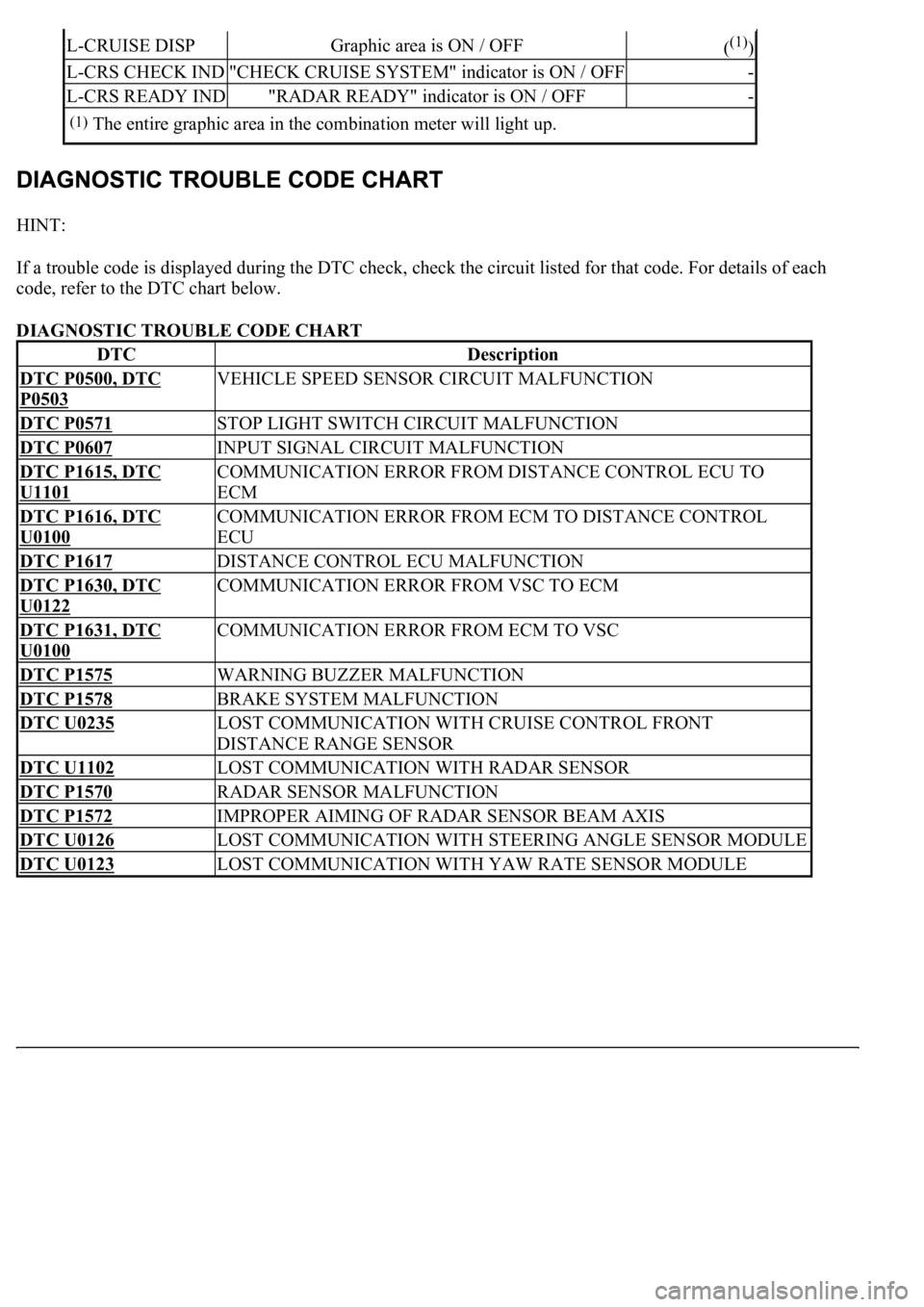
HINT:
If a trouble code is displayed during the DTC check, check the circuit listed for that code. For details of each
code, refer to the DTC chart below.
DIAGNOSTIC TROUBLE CODE CHART
L-CRUISE DISPGraphic area is ON / OFF((1))
L-CRS CHECK IND"CHECK CRUISE SYSTEM" indicator is ON / OFF-
L-CRS READY IND"RADAR READY" indicator is ON / OFF-
(1)The entire graphic area in the combination meter will light up.
DTCDescription
DTC P0500, DTC
P0503
VEHICLE SPEED SENSOR CIRCUIT MALFUNCTION
DTC P0571STOP LIGHT SWITCH CIRCUIT MALFUNCTION
DTC P0607INPUT SIGNAL CIRCUIT MALFUNCTION
DTC P1615, DTC
U1101
COMMUNICATION ERROR FROM DISTANCE CONTROL ECU TO
ECM
DTC P1616, DTC
U0100
COMMUNICATION ERROR FROM ECM TO DISTANCE CONTROL
ECU
DTC P1617DISTANCE CONTROL ECU MALFUNCTION
DTC P1630, DTC
U0122
COMMUNICATION ERROR FROM VSC TO ECM
DTC P1631, DTC
U0100
COMMUNICATION ERROR FROM ECM TO VSC
DTC P1575WARNING BUZZER MALFUNCTION
DTC P1578BRAKE SYSTEM MALFUNCTION
DTC U0235LOST COMMUNICATION WITH CRUISE CONTROL FRONT
DISTANCE RANGE SENSOR
DTC U1102LOST COMMUNICATION WITH RADAR SENSOR
DTC P1570RADAR SENSOR MALFUNCTION
DTC P1572IMPROPER AIMING OF RADAR SENSOR BEAM AXIS
DTC U0126LOST COMMUNICATION WITH STEERING ANGLE SENSOR MODULE
DTC U0123LOST COMMUNICATION WITH YAW RATE SENSOR MODULE
Page 2503 of 4500

CIRCUIT DESCRIPTION
This circuit provides power to operate the laser sensor.
The laser sensor emits laser beams towards an object in front and measures the distance and direction of the
object by receiving the beam reflections. Based on the reflections, the sensor calculates the difference in speed
between your own vehicle and an object in front. This data is transmitted to the cruise control ECU (distance
control ECU).
HINT:
The laser sensor monitors the laser emission and reception by itself. This DTC is detected when it cannot
monitor.
When rain drops or snowflakes strike the laser sensor face, the distance between the vehicle in front and your
own vehicle cannot be measured correctly.
The dynamic laser cruise control system functions by detecting the reflector of the vehicle directly in front. In
the following cases, the system may not be able to detect the vehicle in front and may not properly maintain the
correct vehicle-to-vehicle distance.
The vehicle in front is a tall trailer.
The back of the vehicle in front is extremely dirty.
Emissions from the vehicle in front or from other lanes are heavy.
The vehicle in front has no reflector.
The laser sensor is receiving a strong flash of light (sunlight, etc.).
WIRING DIAGRAM