Page 2599 of 4500
Courtesy of TOYOTA MOTOR SALES, U.S.A., INC.
HINT:
If the beam axis deviates to the distance 4.0 to 6.0 m, upper/lower side +/-2° or more and/or the right/left side
+/-4° or more, this DTC is detected.
INSPECTION PROCEDURE
1.ADJUST MILLIMETER WAVE RADAR SENSOR ASSY (SEE ADJUSTMENT
)
CIRCUIT DESCRIPTION
This circuit detects the angle and direction of steering and automatically transmits its signal to the skid control
ECU and distance control ECU.
Fig. 72: DTC U0126 Problem Symptom Diagnostic Chart
Courtesy of TOYOTA MOTOR SALES, U.S.A., INC.
INSPECTION PROCEDURE
HINT:
This circuit uses CAN for communication. Therefore, if there are any malfunctions in the communication
circuit, one or more DTCs in the CAN communication system is/are output.
1.GO TO CAN COMMUNICATION SYSTEM (SEE PRECAUTION
)
CIRCUIT DESCRIPTION
This circuit detects the yaw rate of the vehicle and transmits its signal to the skid control ECU and distance
control ECU.
Page 2603 of 4500

CIRCUIT DESCRIPTION
This circuit provides power to operate the millimeter wave radar sensor.
The millimeter wave radar sensor emits radar beams towards an object in front and measures the distance and
direction of the object by receiving the beam reflections. Based on the reflections, the sensor calculates the
difference in speed between your own vehicle and an object in front. This data is transmitted to the cruise
control ECU (distance control ECU).
HINT:
The millimeter wave radar sensor monitors the radar emission and reception by itself. This DTC is detected
when it cannot monitor.
When rain drops or snowflakes strike the radar sensor face, the distance between the vehicle in front and your
own vehicle cannot be measured correctly.
The dynamic radar cruise control system functions by detecting the reflector of the vehicle directly in front.
In the following cases, the system may not be able to detect the vehicle in front and may not properly maintain
the correct vehicle-to-vehicle distance.
The vehicle in front is a tall trailer.
Emissions from the vehicle in front or from other lanes are heavy.
WIRING DIAGRAM
Page 2630 of 4500

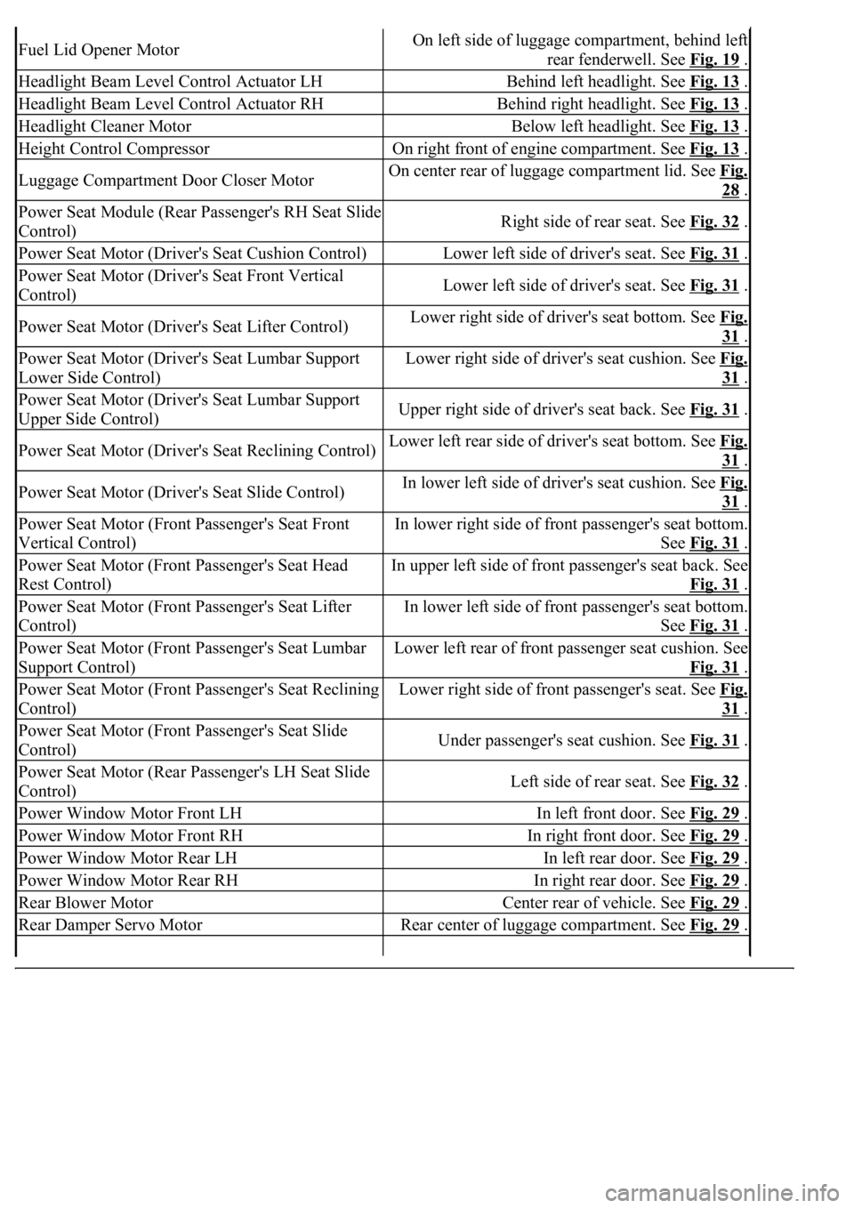
Fuel Lid Opener MotorOn left side of luggage compartment, behind left
rear fenderwell. See Fig. 19
.
Headlight Beam Level Control Actuator LHBehind left headlight. See Fig. 13 .
Headlight Beam Level Control Actuator RHBehind right headlight. See Fig. 13 .
Headlight Cleaner MotorBelow left headlight. See Fig. 13 .
Height Control CompressorOn right front of engine compartment. See Fig. 13 .
Luggage Compartment Door Closer MotorOn center rear of luggage compartment lid. See Fig.
28 .
Power Seat Module (Rear Passenger's RH Seat Slide
Control)Right side of rear seat. See Fig. 32 .
Power Seat Motor (Driver's Seat Cushion Control)Lower left side of driver's seat. See Fig. 31 .
Power Seat Motor (Driver's Seat Front Vertical
Control)Lower left side of driver's seat. See Fig. 31 .
Power Seat Motor (Driver's Seat Lifter Control)Lower right side of driver's seat bottom. See Fig.
31 .
Power Seat Motor (Driver's Seat Lumbar Support
Lower Side Control)Lower right side of driver's seat cushion. See Fig.
31 .
Power Seat Motor (Driver's Seat Lumbar Support
Upper Side Control)Upper right side of driver's seat back. See Fig. 31 .
Power Seat Motor (Driver's Seat Reclining Control)Lower left rear side of driver's seat bottom. See Fig.
31 .
Power Seat Motor (Driver's Seat Slide Control)In lower left side of driver's seat cushion. See Fig.
31 .
Power Seat Motor (Front Passenger's Seat Front
Vertical Control)In lower right side of front passenger's seat bottom.
See Fig. 31
.
Power Seat Motor (Front Passenger's Seat Head
Rest Control)In upper left side of front passenger's seat back. See
Fig. 31
.
Power Seat Motor (Front Passenger's Seat Lifter
Control)In lower left side of front passenger's seat bottom.
See Fig. 31
.
Power Seat Motor (Front Passenger's Seat Lumbar
Support Control)Lower left rear of front passenger seat cushion. See
Fig. 31
.
Power Seat Motor (Front Passenger's Seat Reclining
Control)Lower right side of front passenger's seat. See Fig.
31 .
Power Seat Motor (Front Passenger's Seat Slide
Control)Under passenger's seat cushion. See Fig. 31 .
Power Seat Motor (Rear Passenger's LH Seat Slide
Control)Left side of rear seat. See Fig. 32 .
Power Window Motor Front LHIn left front door. See Fig. 29 .
Power Window Motor Front RHIn right front door. See Fig. 29 .
Power Window Motor Rear LHIn left rear door. See Fig. 29 .
Power Window Motor Rear RHIn right rear door. See Fig. 29 .
Rear Blower MotorCenter rear of vehicle. See Fig. 29 .
Rear Damper Servo MotorRear center of luggage compartment. See Fig. 29 .
Page 4258 of 4500
Installation is in the reverse order of removal.
See COMPONENTS .
1.DISCONNECT NEGATIVE TERMINAL CABLE FROM BATTERY
2.REMOVE FRONT DOOR SCUFF PLATE LH (See REPLACEMENT
)
3.REMOVE FRONT PILLAR GARNISH LH (See step 33 in REPLACEMENT
)
4.REMOVE INSTRUMENT PANEL UNDER COVER SUB-ASSY NO. 2 (See step 21 in
REPLACEMENT
)
5.REMOVE INSTRUMENT PANEL GARNISH SUB-ASSY RH (See step 22 in REPLACEMENT
)
6.REMOVE GLOVE COMPARTMENT DOOR ASSY W/ INSTRUMENT PANEL AIRBAG ASSY
LOWER NO. 2 (See step 25 in REPLACEMENT
)
7.REMOVE AIR SUSPENSION AND HEADLIGHT BEAM LEVEL CONTROL ECU
a. Disconnect the connectors.
b. Remove the 2 nuts and air suspension and headlight beam level control ECU.
8.REMOVE BLOWER ASSY
a. Disconnect the connectors.
b. Remove the nut and 3 bolts.
c. Remove the blower assy.