Page 730 of 4500
1.RADIO RECEIVER ASSY (Physical address: 190) [AUDIO H/U]
a. Logical address: 01 (Communication control)
HINT:
Methods used to verify the cause of the problem are listed in order of probability in the verification
column.
Fig. 25: DTC Detecting Condition Chart
Courtesy of TOYOTA MOTOR SALES, U.S.A., INC.
HINT:
*1: Even if no failure is detected, a trouble code may be recorded depending on the battery
condition or engine start voltage.
*2: If the power connector is disconnected after the engine starts, this code is recorded after
180 seconds.
*3: This code may be stored if the ignition key is turned again after the engine starts.
Page 735 of 4500
![LEXUS LS430 2003 Factory Repair Manual Fig. 28: DTC Detecting Condition Chart (Physical address: 17D) [TEL])
Courtesy of TOYOTA MOTOR SALES, U.S.A., INC.
HINT:
*1: Even if no failure is detected, a trouble code may be recorded depending LEXUS LS430 2003 Factory Repair Manual Fig. 28: DTC Detecting Condition Chart (Physical address: 17D) [TEL])
Courtesy of TOYOTA MOTOR SALES, U.S.A., INC.
HINT:
*1: Even if no failure is detected, a trouble code may be recorded depending](/manual-img/36/57050/w960_57050-734.png)
Fig. 28: DTC Detecting Condition Chart (Physical address: 17D) [TEL])
Courtesy of TOYOTA MOTOR SALES, U.S.A., INC.
HINT:
*1: Even if no failure is detected, a trouble code may be recorded depending on the battery
condition or engine start voltage.
*2: If the power connector is disconnected after the engine starts, this code is recorded after
180 seconds.
*3: This code may be stored if the ignition key is turned again after the engine starts.
*4: This code may be stored if the ignition key is held in the START position for one minute
or more before returning to the ON position.
*5: If the device is reported as not existing during verification, check the power source circuit
and AVC-LAN circuit for the device.
b. Logical address: 57 (telephone information drawing): 68 (TEL)
HINT:
Methods used to verify the cause of the problem are listed in order of probability in the verification
column.
Fig. 29: DTC Detecting Condition Chart
Courtesy of TOYOTA MOTOR SALES, U.S.A., INC.
3.AUDIO AND REAR A/C CONTROL SW (Physical address: 1CO) [Rr-CONT]
a. Logical address: 01 (Communication control)
HINT:
Methods used to verify the cause of the problem are listed in order of probability in the verification
column.
Page 737 of 4500
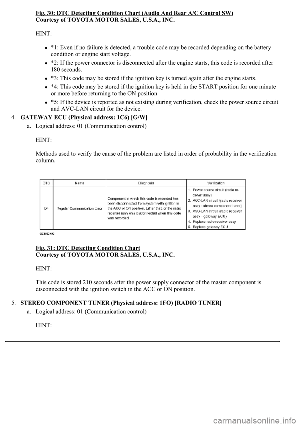
Fig. 30: DTC Detecting Condition Chart (Audio And Rear A/C Control SW)
Courtesy of TOYOTA MOTOR SALES, U.S.A., INC.
HINT:
*1: Even if no failure is detected, a trouble code may be recorded depending on the battery
condition or engine start voltage.
*2: If the power connector is disconnected after the engine starts, this code is recorded after
180 seconds.
*3: This code may be stored if the ignition key is turned again after the engine starts.
*4: This code may be stored if the ignition key is held in the START position for one minute
or more before returning to the ON position.
*5: If the device is reported as not existing during verification, check the power source circuit
and AVC-LAN circuit for the device.
4.GATEWAY ECU (Physical address: 1C6) [G/W]
a. Logical address: 01 (Communication control)
HINT:
Methods used to verify the cause of the problem are listed in order of probability in the verification
column.
Fig. 31: DTC Detecting Condition Chart
Courtesy of TOYOTA MOTOR SALES, U.S.A., INC.
HINT:
This code is stored 210 seconds after the power supply connector of the master component is
disconnected with the ignition switch in the ACC or ON position.
5.STEREO COMPONENT TUNER (Physical address: 1FO) [RADIO TUNER]
a. Logical address: 01 (Communication control)
HINT:
Page 739 of 4500
HINT:
*1: Even if no failure is detected, a trouble code may be recorded depending on the battery
condition or engine start voltage.
*2: If the power connector is disconnected after the engine starts, this code is recorded after
180 seconds.
*3: This code may be stored if the ignition key is turned again after the engine starts.
*4: This code may be stored if the ignition key is held in the START position for one minute
or more before returning to the ON position.
*5: If the device is reported as not existing during verification, check the power source circuit
and AVC-LAN circuit for the device.
b. Logical address: 60 (Radio)
HINT:
Methods used to verify the cause of the problem are listed in order of probability in the verification
column.
Fig. 33: DTC Detecting Condition Chart
Courtesy of TOYOTA MOTOR SALES, U.S.A., INC.
Page 742 of 4500
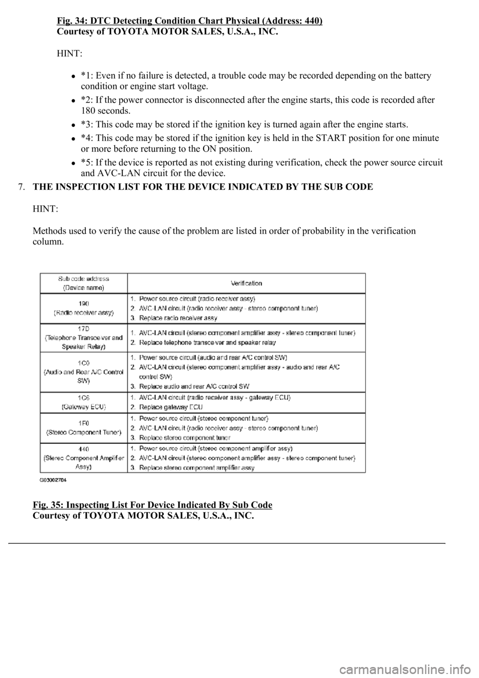
Fig. 34: DTC Detecting Condition Chart Physical (Address: 440)
Courtesy of TOYOTA MOTOR SALES, U.S.A., INC.
HINT:
*1: Even if no failure is detected, a trouble code may be recorded depending on the battery
condition or engine start voltage.
*2: If the power connector is disconnected after the engine starts, this code is recorded after
180 seconds.
*3: This code may be stored if the ignition key is turned again after the engine starts.
*4: This code may be stored if the ignition key is held in the START position for one minute
or more before returning to the ON position.
*5: If the device is reported as not existing during verification, check the power source circuit
and AVC-LAN circuit for the device.
7.THE INSPECTION LIST FOR THE DEVICE INDICATED BY THE SUB CODE
HINT:
Methods used to verify the cause of the problem are listed in order of probability in the verification
column.
Fig. 35: Inspecting List For Device Indicated By Sub Code
Courtesy of TOYOTA MOTOR SALES, U.S.A., INC.
Page 929 of 4500
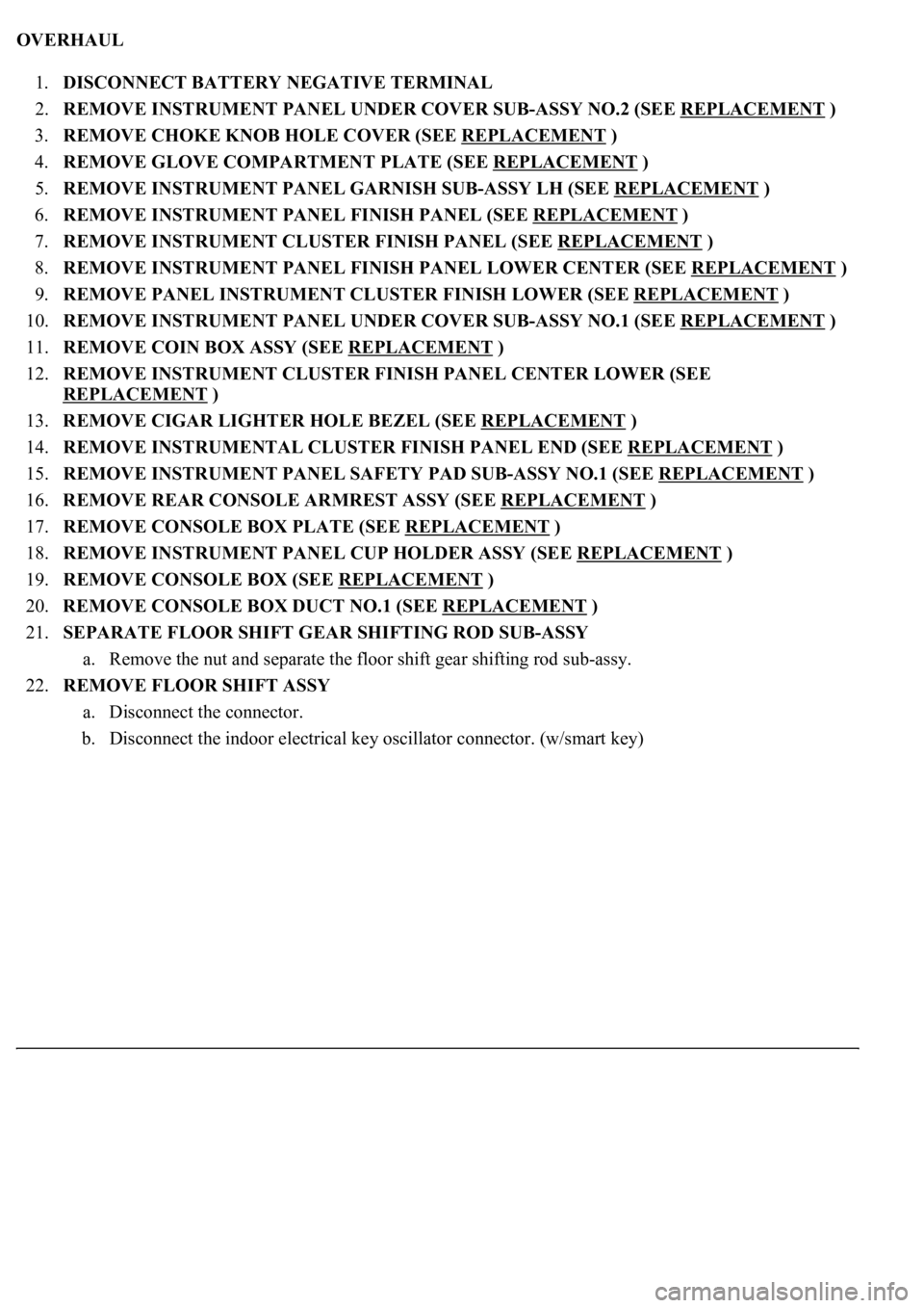
OVERHAUL
1.DISCONNECT BATTERY NEGATIVE TERMINAL
2.REMOVE INSTRUMENT PANEL UNDER COVER SUB-ASSY NO.2 (SEE REPLACEMENT
)
3.REMOVE CHOKE KNOB HOLE COVER (SEE REPLACEMENT
)
4.REMOVE GLOVE COMPARTMENT PLATE (SEE REPLACEMENT
)
5.REMOVE INSTRUMENT PANEL GARNISH SUB-ASSY LH (SEE REPLACEMENT
)
6.REMOVE INSTRUMENT PANEL FINISH PANEL (SEE REPLACEMENT
)
7.REMOVE INSTRUMENT CLUSTER FINISH PANEL (SEE REPLACEMENT
)
8.REMOVE INSTRUMENT PANEL FINISH PANEL LOWER CENTER (SEE REPLACEMENT
)
9.REMOVE PANEL INSTRUMENT CLUSTER FINISH LOWER (SEE REPLACEMENT
)
10.REMOVE INSTRUMENT PANEL UNDER COVER SUB-ASSY NO.1 (SEE REPLACEMENT
)
11.REMOVE COIN BOX ASSY (SEE REPLACEMENT
)
12.REMOVE INSTRUMENT CLUSTER FINISH PANEL CENTER LOWER (SEE
REPLACEMENT
)
13.REMOVE CIGAR LIGHTER HOLE BEZEL (SEE REPLACEMENT
)
14.REMOVE INSTRUMENTAL CLUSTER FINISH PANEL END (SEE REPLACEMENT
)
15.REMOVE INSTRUMENT PANEL SAFETY PAD SUB-ASSY NO.1 (SEE REPLACEMENT
)
16.REMOVE REAR CONSOLE ARMREST ASSY (SEE REPLACEMENT
)
17.REMOVE CONSOLE BOX PLATE (SEE REPLACEMENT
)
18.REMOVE INSTRUMENT PANEL CUP HOLDER ASSY (SEE REPLACEMENT
)
19.REMOVE CONSOLE BOX (SEE REPLACEMENT
)
20.REMOVE CONSOLE BOX DUCT NO.1 (SEE REPLACEMENT
)
21.SEPARATE FLOOR SHIFT GEAR SHIFTING ROD SUB-ASSY
a. Remove the nut and separate the floor shift gear shifting rod sub-assy.
22.REMOVE FLOOR SHIFT ASSY
a. Disconnect the connector.
b. Disconnect the indoor electrical key oscillator connector. (w/smart key)
Page 1517 of 4500
Courtesy of TOYOTA MOTOR SALES, U.S.A., INC.
HINT:
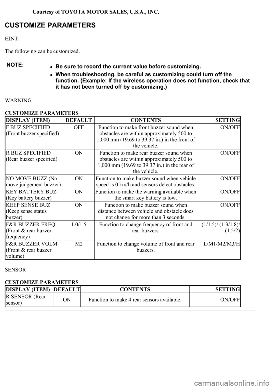
The following can be customized.
WARNING
CUSTOMIZE PARAMETERS
SENSOR
CUSTOMIZE PARAMETERS
DISPLAY (ITEM)DEFAULTCONTENTSSETTING
F BUZ SPECIFIED
(Front buzzer specified)OFFFunction to make front buzzer sound when
obstacles are within approximately 500 to
1,000 mm (19.69 to 39.37 in.) in the front of
the vehicle.ON/OFF
R BUZ SPECIFIED
(Rear buzzer specified)ONFunction to make rear buzzer sound when
obstacles are within approximately 500 to
1,000 mm (19.69 to 39.37 in.) in the rear of
the vehicle.ON/OFF
NO MOVE BUZZ (No
move judgement buzzer)ONFunction to make buzzer sound when vehicle
speed is 0 km/h and sensors detect obstacles.ON/OFF
KEY BATTERY BUZ
(Key battery buzzer)ONFunction to make the warning available when
the smart key battery is low.ON/OFF
KEEP SENSE BUZ
(Keep sense status
buzzer)ONFunction to make buzzer sound when
distance between vehicle and obstacle does
not change for more than 3 seconds.ON/OFF
F&R BUZZER FREQ
(Front & rear buzzer
frequency)1.0/1.5Function to change frequency of front and
rear buzzers.(1/1.5)/ (1.3/1.8)/
(1.5/2)
F&R BUZZER VOLM
(Front & rear buzzer
volume)M2Function to change volume of front and rear
buzzers.L/M1/M2/M3/H
DISPLAY (ITEM)DEFAULTCONTENTSSETTING
R SENSOR (Rear
sensor)ONFunction to make 4 rear sensors available.ON/OFF
Page 3242 of 4500
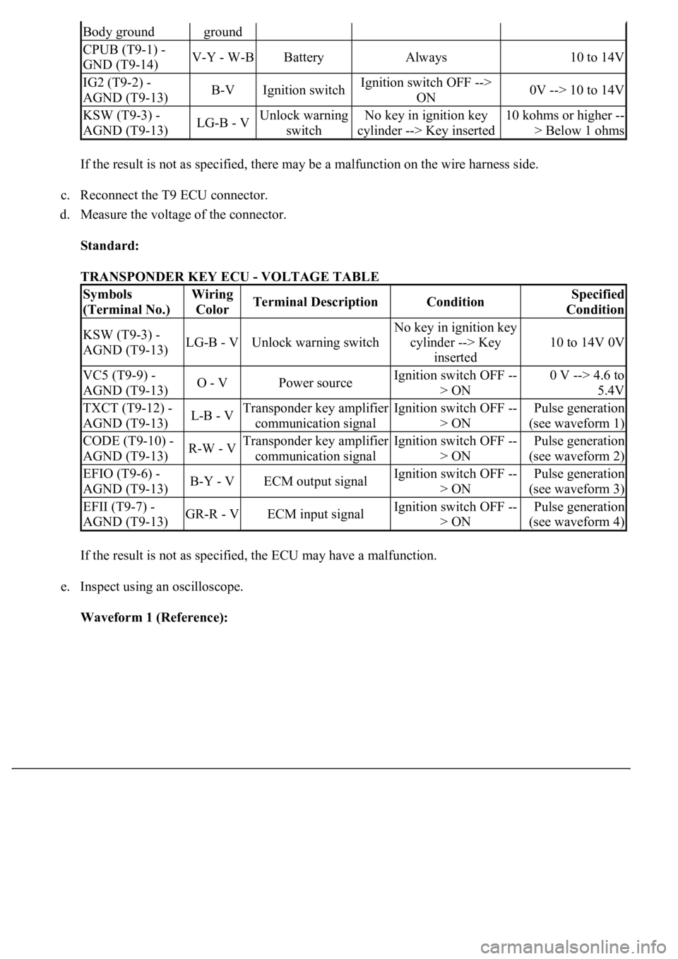
If the result is not as specified, there may be a malfunction on the wire harness side.
c. Reconnect the T9 ECU connector.
d. Measure the voltage of the connector.
Standard:
TRANSPONDER KEY ECU - VOLTAGE TABLE
If the result is not as specified, the ECU may have a malfunction.
e. Inspect using an oscilloscope.
Waveform 1 (Reference):
Body groundground
CPUB (T9-1) -
GND (T9-14)V-Y - W-BBatteryAlways10 to 14V
IG2 (T9-2) -
AGND (T9-13)B-VIgnition switchIgnition switch OFF -->
ON0V --> 10 to 14V
KSW (T9-3) -
AGND (T9-13)LG-B - VUnlock warning
switchNo key in ignition key
cylinder --> Key inserted10 kohms or higher --
> Below 1 ohms
Symbols
(Terminal No.)Wiring
ColorTerminal DescriptionConditionSpecified
Condition
KSW (T9-3) -
AGND (T9-13)LG-B - VUnlock warning switch
No key in ignition key
cylinder --> Key
inserted
10 to 14V 0V
VC5 (T9-9) -
AGND (T9-13)O - VPower sourceIgnition switch OFF --
> ON0 V --> 4.6 to
5.4V
TXCT (T9-12) -
AGND (T9-13)L-B - VTransponder key amplifier
communication signalIgnition switch OFF --
> ONPulse generation
(see waveform 1)
CODE (T9-10) -
AGND (T9-13)R-W - VTransponder key amplifier
communication signalIgnition switch OFF --
> ONPulse generation
(see waveform 2)
EFIO (T9-6) -
AGND (T9-13)B-Y - VECM output signalIgnition switch OFF --
> ONPulse generation
(see waveform 3)
EFII (T9-7) -
AGND (T9-13)GR-R - VECM input signalIgnition switch OFF --
> ONPulse generation
(see waveform 4)