Page 6 of 4500

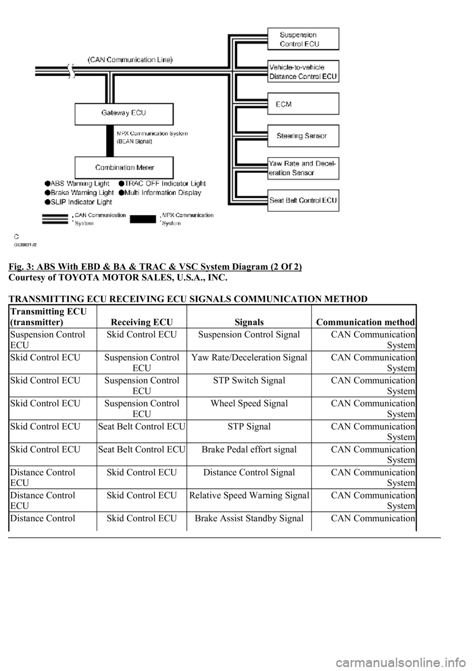
Fig. 3: ABS With EBD & BA & TRAC & VSC System Diagram (2 Of 2)
Courtesy of TOYOTA MOTOR SALES, U.S.A., INC.
TRANSMITTING ECU RECEIVING ECU SIGNALS COMMUNICATION METHOD
Transmitting ECU
(transmitter)
Receiving ECUSignalsCommunication method
Suspension Control
ECUSkid Control ECUSuspension Control SignalCAN Communication
System
Skid Control ECUSuspension Control
ECUYaw Rate/Deceleration SignalCAN Communication
System
Skid Control ECUSuspension Control
ECUSTP Switch SignalCAN Communication
System
Skid Control ECUSuspension Control
ECUWheel Speed SignalCAN Communication
System
Skid Control ECUSeat Belt Control ECUSTP SignalCAN Communication
System
Skid Control ECUSeat Belt Control ECUBrake Pedal effort signalCAN Communication
System
Distance Control
ECUSkid Control ECUDistance Control SignalCAN Communication
System
Distance Control
ECUSkid Control ECURelative Speed Warning SignalCAN Communication
System
Distance Control Skid Control ECUBrake Assist Standby SignalCAN Communication
Page 11 of 4500
Fig. 7: ABS & TRACTION Actuator - Traction Control
Courtesy of TOYOTA MOTOR SALES, U.S.A., INC.
Operation description
The skid control ECU detects vehicle's slip condition by receiving signals from the speed sensor
<004400510047000300280026003000030059004c004400030026002400310003004600520050005000580051004c004600440057004c00520051001100030037004b004800030056004e004c00470003004600520051005700550052004f00030028002600
380003004600520051005700550052004f0056000300480051[gine torque with the ECM,
vehicle position with suspension control ECU via CAN communication, and oil pressure with the
pump and solenoid valve. The SLIP indicator lamp blinks when the system is operating. TRAC
OFF switch stops traction control operation.
e. VSC (Vehicle Stability Control)
The VSC system helps prevent the vehicle from slipping sideways as a result of strong front wheel skid or
stron
g rear wheel skid during cornering.
Page 12 of 4500

Fig. 8: ABS & TRACTION Actuator - Vehicle Stability Control
Courtesy of TOYOTA MOTOR SALES, U.S.A., INC.
Operation description
The skid control ECU determines vehicle condition by receiving signals from the speed sensor, yaw rate
and deceleration sensor and steering angle sensor. The skid control ECU controls engine torque with the
ECM, vehicle position with suspension control ECU via CAN communication, and oil pressure with the
pump and solenoid valve. The warning light comes on and the buzzer sounds when the system is
operating.
2.ABS with EBD & BA & TRAC & VSC OPERATION
a. Skid control ECU calculates vehicle stability tendency based on the signal of sensors, speed sensor,
yaw rate and deceleration sensor and steering angle sensor. And it judges whether the control of
engine output torque by electronic control throttle and of wheel brake pressure by brake actuator
will operate or not by the calculation results.
b. The SLIP indicator blinks and the VSC buzzer sounds to inform the driver that the VSC system is
operating. The SLIP indicator also blinks when TRAC is operating, and the operation being
performed is displayed.
3.FAIL SAFE FUNCTION
a. When a failure occurs in the ABS with BA & TRAC & VSC systems, the ABS warning light and
the VSC warning light turns on and the ABS with BA & TRAC & VSC operations are prohibited.
In addition to this, when there is a failure that disables the EBD operation, the brake warning light
also comes on and the EBD operation is prohibited (see FAIL
-SAFE CHART ).
b. If some control is prohibited due to a malfunction during it's operation, that control will be cut off
gradually not to change stability of vehicle suddenly.
4.PRE-COLLISION BRAKE ASSIST SYSTEM (w/ PRE-COLLISION BRAKE ASSIST SYSTEM)
Page 469 of 4500

If the vehicle is raised with its engine running, connect terminals OPB and CG of the DLC3 to stop
the vehicle height control operation of the suspension control ECU.
Do not operate the steering wheel if there is no air in the pneumatic cylinder.
HINT:
The pneumatic cylinder could be damaged if twisted without air in the cylinder.
In the case of lifting down the vehicle without air in the cylinder, make sure all the pipes are securely
connected.
HINT:
The pneumatic cylinder could be damaged if any pipe is disconnected while lifting down the vehicle.
Do not apply battery voltage to the compressor motor for more than 60 seconds to prevent damage to the
motor.
HINT:
When it is necessary to perform the operation by charging the battery for more than 60 seconds, for example
height recovery without air in the cylinder, proceed to the operation as follows: after 60 seconds have passed,
turn the ignition switch off once, and then turn the ignition switch to the ON position again for commencement
of operation.
Page 470 of 4500
Fig. 2: Identifying Air Suspension System Components Location
Courtesy of TOYOTA MOTOR SALES, U.S.A., INC.
Page 471 of 4500
Fig. 3: Air Suspension System Diagram
Courtesy of TOYOTA MOTOR SALES, U.S.A., INC.
1.AIR SUSPENSION SYSTEM DESCRIPTION
Page 472 of 4500

a. The suspension control ECU operates the compressor & motor with the dryer and uses the solenoid
valves to control the vehicle height by analyzing the information based on the switches, sensors and
input signals.
b. Through the 4 height control sensors, the suspension control ECU detects the changes in the vehicle
height that results from the number of occupants or the amount of the load. Then, the suspension
control ECU controls the height control solenoid valves and the compressor & motor with the dryer
in order to automatically adjust the vehicle height to a constant (normal) level.
c. Furthermore, two vehicle heights can be selected by operating the height control switch: HI and
Normal.
d. In cases such as when the vehicle is jacked up, the auto leveling function is prohibited by turning
the ignition switch off.
If the vehicle is raised with its engine running, connect terminals OPB and CG of the DLC3 so the
vehicle height control is not carried out.
e. The absorber control switch selects the shock absorber damping force (normal or sport).
f. w/ Pre-collision safety system:
The suspension control ECU changes the stiffness of the suspension to the hardest setting by
receiving signals (collision unavoidable) from the cruise control ECU.
Function of Components
Page 475 of 4500
Fig. 5: Air Suspension System Check Sheet
Courtesy of TOYOTA MOTOR SALES, U.S.A., INC.
1.TEST MODE