2003 LEXUS LS430 cruise control
[x] Cancel search: cruise controlPage 472 of 4500

a. The suspension control ECU operates the compressor & motor with the dryer and uses the solenoid
valves to control the vehicle height by analyzing the information based on the switches, sensors and
input signals.
b. Through the 4 height control sensors, the suspension control ECU detects the changes in the vehicle
height that results from the number of occupants or the amount of the load. Then, the suspension
control ECU controls the height control solenoid valves and the compressor & motor with the dryer
in order to automatically adjust the vehicle height to a constant (normal) level.
c. Furthermore, two vehicle heights can be selected by operating the height control switch: HI and
Normal.
d. In cases such as when the vehicle is jacked up, the auto leveling function is prohibited by turning
the ignition switch off.
If the vehicle is raised with its engine running, connect terminals OPB and CG of the DLC3 so the
vehicle height control is not carried out.
e. The absorber control switch selects the shock absorber damping force (normal or sport).
f. w/ Pre-collision safety system:
The suspension control ECU changes the stiffness of the suspension to the hardest setting by
receiving signals (collision unavoidable) from the cruise control ECU.
Function of Components
Page 1200 of 4500
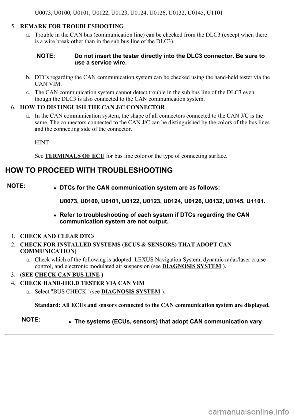
U0073, U0100, U0101, U0122, U0123, U0124, U0126, U0132, U0145, U1101
5.REMARK FOR TROUBLESHOOTING
a. Trouble in the CAN bus (communication line) can be checked from the DLC3 (except when there
is a wire break other than in the sub bus line of the DLC3).
b. DTCs regarding the CAN communication system can be checked using the hand-held tester via the
CAN VIM.
c. The CAN communication system cannot detect trouble in the sub bus line of the DLC3 even
though the DLC3 is also connected to the CAN communication system.
6.HOW TO DISTINGUISH THE CAN J/C CONNECTOR
a. In the CAN communication system, the shape of all connectors connected to the CAN J/C is the
same. The connectors connected to the CAN J/C can be distinguished by the colors of the bus lines
and the connecting side of the connector.
HINT:
See TERMINALS OF ECU
for bus line color or the type of connecting surface.
1.CHECK AND CLEAR DTCs
2.CHECK FOR INSTALLED SYSTEMS (ECUS & SENSORS) THAT ADOPT CAN
COMMUNICATION)
a. Check which of the following is adopted: LEXUS Navigation System, dynamic radar/laser cruise
control, and electronic modulated air suspension (see DIAGNOSIS SYSTEM
).
3.(SEE CHECK CAN BUS LINE
)
4.CHECK HAND-HELD TESTER VIA CAN VIM
a. Select "BUS CHECK" (see DIAGNOSIS SYSTEM
).
Standard: All ECUs and sensors connected to the CAN communication system are displayed.
Page 1206 of 4500
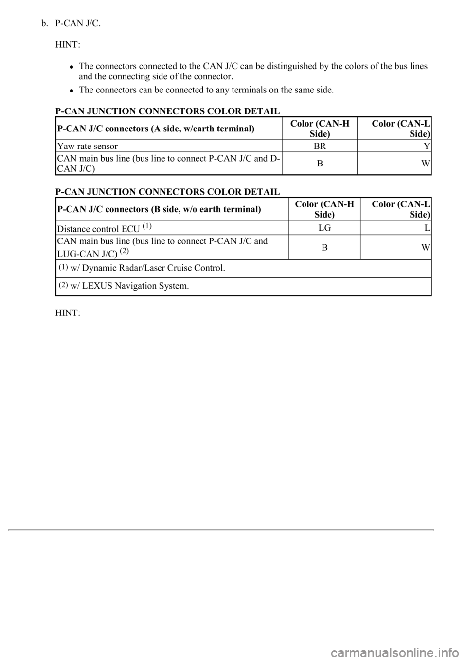
b. P-CAN J/C.
HINT:
The connectors connected to the CAN J/C can be distinguished by the colors of the bus lines
and the connecting side of the connector.
<0037004b00480003004600520051005100480046005700520055005600030046004400510003004500480003004600520051005100480046005700480047000300570052000300440051005c00030057004800550050004c00510044004f00560003005200
5100030057004b00480003005600440050004800030056004c[de.
P-CAN JUNCTION CONNECTORS COLOR DETAIL
P-CAN JUNCTION CONNECTORS COLOR DETAIL
HINT:
P-CAN J/C connectors (A side, w/earth terminal)Color (CAN-H
Side)Color (CAN-L
Side)
Yaw rate sensorBRY
CAN main bus line (bus line to connect P-CAN J/C and D-
CAN J/C)BW
P-CAN J/C connectors (B side, w/o earth terminal)Color (CAN-H
Side)Color (CAN-L
Side)
Distance control ECU (1)LGL
CAN main bus line (bus line to connect P-CAN J/C and
LUG-CAN J/C)
(2)BW
(1)w/ Dynamic Radar/Laser Cruise Control.
(2)w/ LEXUS Navigation System.
Page 1223 of 4500
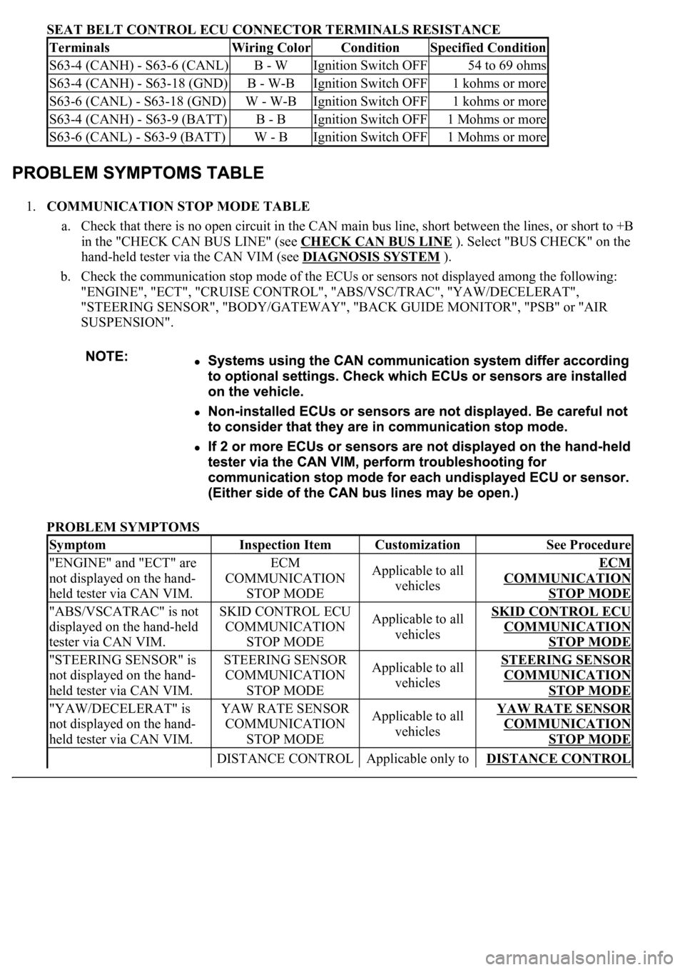
SEAT BELT CONTROL ECU CONNECTOR TERMINALS RESISTANCE
1.COMMUNICATION STOP MODE TABLE
a. Check that there is no open circuit in the CAN main bus line, short between the lines, or short to +B
in the "CHECK CAN BUS LINE" (see CHECK CAN BUS LINE
). Select "BUS CHECK" on the
hand-held tester via the CAN VIM (see DIAGNOSIS SYSTEM
).
b. Check the communication stop mode of the ECUs or sensors not displayed among the following:
"ENGINE", "ECT", "CRUISE CONTROL", "ABS/VSC/TRAC", "YAW/DECELERAT",
"STEERING SENSOR", "BODY/GATEWAY", "BACK GUIDE MONITOR", "PSB" or "AIR
SUSPENSION".
PROBLEM SYMPTOMS
TerminalsWiring ColorConditionSpecified Condition
S63-4 (CANH) - S63-6 (CANL)B - WIgnition Switch OFF54 to 69 ohms
S63-4 (CANH) - S63-18 (GND)B - W-BIgnition Switch OFF1 kohms or more
S63-6 (CANL) - S63-18 (GND)W - W-BIgnition Switch OFF1 kohms or more
S63-4 (CANH) - S63-9 (BATT)B - BIgnition Switch OFF1 Mohms or more
S63-6 (CANL) - S63-9 (BATT)W - BIgnition Switch OFF1 Mohms or more
SymptomInspection ItemCustomizationSee Procedure
"ENGINE" and "ECT" are
not displayed on the hand-
held tester via CAN VIM.ECM
COMMUNICATION
STOP MODEApplicable to all
vehiclesECM
COMMUNICATION
STOP MODE
"ABS/VSCATRAC" is not
displayed on the hand-held
tester via CAN VIM.SKID CONTROL ECU
COMMUNICATION
STOP MODEApplicable to all
vehiclesSKID CONTROL ECU
COMMUNICATION
STOP MODE
"STEERING SENSOR" is
not displayed on the hand-
held tester via CAN VIM.STEERING SENSOR
COMMUNICATION
STOP MODEApplicable to all
vehiclesSTEERING SENSOR
COMMUNICATION
STOP MODE
"YAW/DECELERAT" is
not displayed on the hand-
held tester via CAN VIM.YAW RATE SENSOR
COMMUNICATION
STOP MODEApplicable to all
vehiclesYAW RATE SENSOR
COMMUNICATION
STOP MODE
DISTANCE CONTROL Applicable only to DISTANCE CONTROL
Page 1224 of 4500
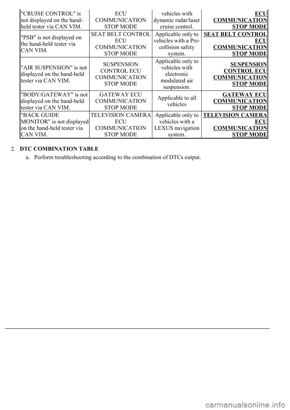
2.DTC COMBINATION TABLE
a. Perform troubleshooting according to the combination of DTCs output.
"CRUISE CONTROL" is
not displayed on the hand-
held tester via CAN VIM.ECU
COMMUNICATION
STOP MODEvehicles with
dynamic radar/laser
cruise control.ECU
COMMUNICATION
STOP MODE
"PSB" is not displayed on
the hand-held tester via
CAN VIM.SEAT BELT CONTROL
ECU
COMMUNICATION
STOP MODEApplicable only to
vehicles with a Pre-
collision safety
system.SEAT BELT CONTROL
ECU
COMMUNICATION
STOP MODE
"AIR SUSPENSION" is not
displayed on the hand-held
tester via CAN VIM.SUSPENSION
CONTROL ECU
COMMUNICATION
STOP MODEApplicable only to
vehicles with
electronic
modulated air
suspension.SUSPENSION
CONTROL ECU
COMMUNICATION
STOP MODE
"BODY/GATEWAY" is not
displayed on the hand-held
tester via CAN VIM.GATEWAY ECU
COMMUNICATION
STOP MODEApplicable to all
vehiclesGATEWAY ECU
COMMUNICATION
STOP MODE
"BACK GUIDE
MONITOR" is not displayed
on the hand-held tester via
CAN VIM.TELEVISION CAMERA
ECU
COMMUNICATION
STOP MODEApplicable only to
vehicles with a
LEXUS navigation
system.TELEVISION CAMERA
ECU
COMMUNICATION
STOP MODE
Page 1231 of 4500
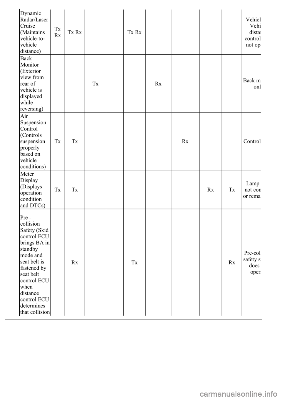
Dynamic
Radar/Laser
Cruise
(Maintains
vehicle-to-
vehicle
distance)
Tx
RxTx Rx Tx Rx
Vehicl
Vehi
dista
n
control
not op
e
Back
Monitor
(Exterior
view from
rear of
vehicle is
displayed
while
reversing)
Tx Rx Back m
onl
Air
Suspension
Control
(Controls
suspension
properly
based on
vehicle
conditions)
TxTx Rx Control
Meter
Display
(Displays
operation
condition
and DTCs)
TxTx RxTx
Lamp
not co
m
or remai
Pre -
collision
Safety (Skid
control ECU
brings BA in
standby
mode and
seat belt is
fastened by
seat belt
control ECU
when
distance
control ECU
determines
that collision
Rx Tx RxPre-col
l
safety sy
does
oper
a
Page 1232 of 4500
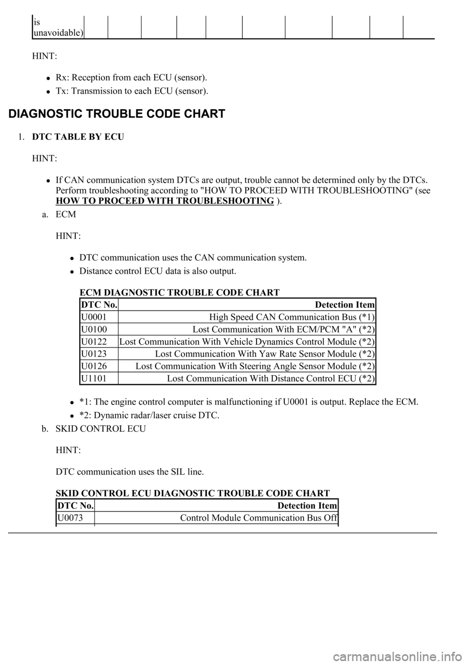
HINT:
Rx: Reception from each ECU (sensor).
Tx: Transmission to each ECU (sensor).
1.DTC TABLE BY ECU
HINT:
If CAN communication system DTCs are output, trouble cannot be determined only by the DTCs.
Perform troubleshooting according to "HOW TO PROCEED WITH TROUBLESHOOTING" (see
HOW TO PROCEED WITH TROUBLESHOOTING
).
a. ECM
HINT:
DTC communication uses the CAN communication system.
Distance control ECU data is also output.
ECM DIAGNOSTIC TROUBLE CODE CHART
*1: The engine control computer is malfunctioning if U0001 is output. Replace the ECM.
*2: Dynamic radar/laser cruise DTC.
b. SKID CONTROL ECU
HINT:
DTC communication uses the SIL line.
SKID CONTROL ECU DIAGNOSTIC TROUBLE CODE CHART
is
unavoidable)
DTC No.Detection Item
U0001High Speed CAN Communication Bus (*1)
U0100Lost Communication With ECM/PCM "A" (*2)
U0122Lost Communication With Vehicle Dynamics Control Module (*2)
U0123Lost Communication With Yaw Rate Sensor Module (*2)
U0126Lost Communication With Steering Angle Sensor Module (*2)
U1101Lost Communication With Distance Control ECU (*2)
DTC No.Detection Item
U0073Control Module Communication Bus Off
Page 1744 of 4500
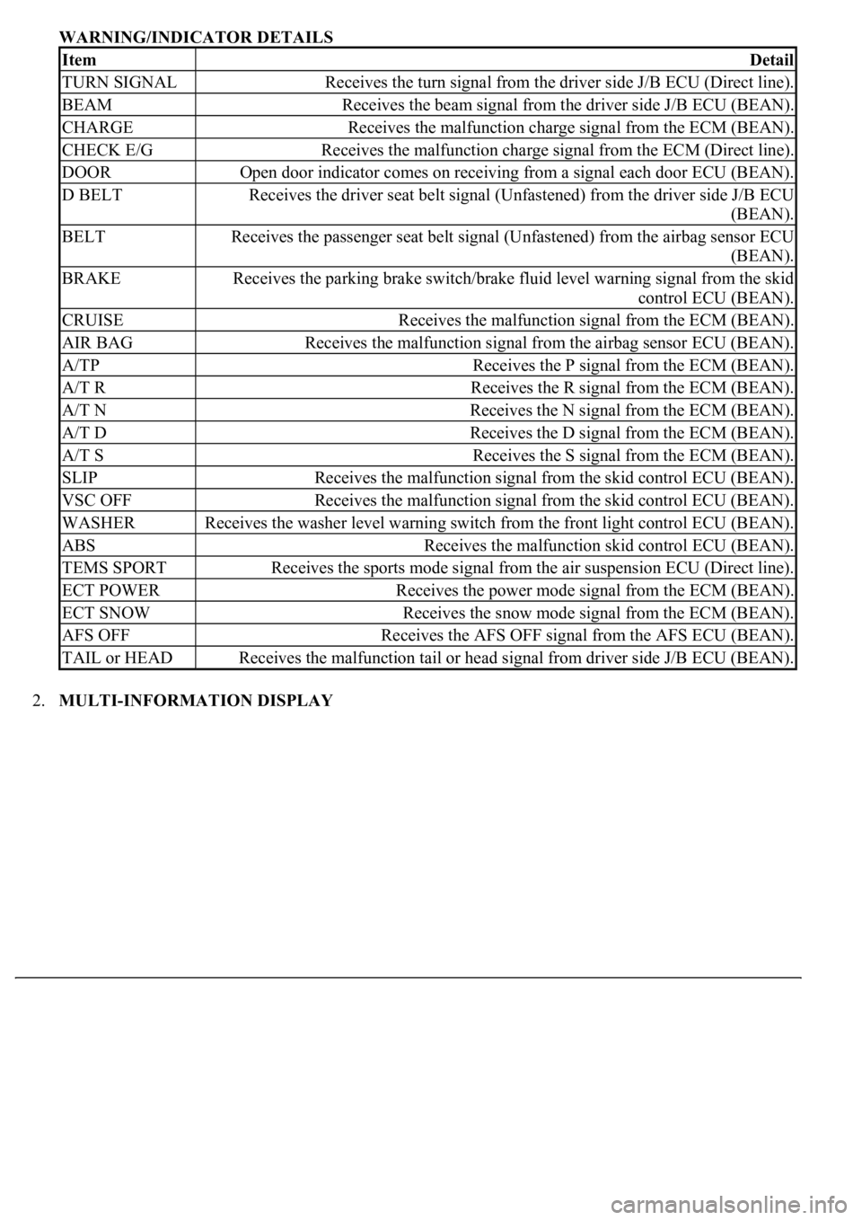
WARNING/INDICATOR DETAILS
2.MULTI-INFORMATION DISPLAY
ItemDetail
TURN SIGNALReceives the turn signal from the driver side J/B ECU (Direct line).
BEAMReceives the beam signal from the driver side J/B ECU (BEAN).
CHARGEReceives the malfunction charge signal from the ECM (BEAN).
CHECK E/GReceives the malfunction charge signal from the ECM (Direct line).
DOOROpen door indicator comes on receiving from a signal each door ECU (BEAN).
D BELTReceives the driver seat belt signal (Unfastened) from the driver side J/B ECU
(BEAN).
BELTReceives the passenger seat belt signal (Unfastened) from the airbag sensor ECU
(BEAN).
BRAKEReceives the parking brake switch/brake fluid level warning signal from the skid
control ECU (BEAN).
CRUISEReceives the malfunction signal from the ECM (BEAN).
AIR BAGReceives the malfunction signal from the airbag sensor ECU (BEAN).
A/TPReceives the P signal from the ECM (BEAN).
A/T RReceives the R signal from the ECM (BEAN).
A/T NReceives the N signal from the ECM (BEAN).
A/T DReceives the D signal from the ECM (BEAN).
A/T SReceives the S signal from the ECM (BEAN).
SLIPReceives the malfunction signal from the skid control ECU (BEAN).
VSC OFFReceives the malfunction signal from the skid control ECU (BEAN).
WASHERReceives the washer level warning switch from the front light control ECU (BEAN).
ABSReceives the malfunction skid control ECU (BEAN).
TEMS SPORTReceives the sports mode signal from the air suspension ECU (Direct line).
ECT POWERReceives the power mode signal from the ECM (BEAN).
ECT SNOWReceives the snow mode signal from the ECM (BEAN).
AFS OFFReceives the AFS OFF signal from the AFS ECU (BEAN).
TAIL or HEADReceives the malfunction tail or head signal from driver side J/B ECU (BEAN).