2003 LEXUS LS430 change wheel
[x] Cancel search: change wheelPage 12 of 4500

Fig. 8: ABS & TRACTION Actuator - Vehicle Stability Control
Courtesy of TOYOTA MOTOR SALES, U.S.A., INC.
Operation description
The skid control ECU determines vehicle condition by receiving signals from the speed sensor, yaw rate
and deceleration sensor and steering angle sensor. The skid control ECU controls engine torque with the
ECM, vehicle position with suspension control ECU via CAN communication, and oil pressure with the
pump and solenoid valve. The warning light comes on and the buzzer sounds when the system is
operating.
2.ABS with EBD & BA & TRAC & VSC OPERATION
a. Skid control ECU calculates vehicle stability tendency based on the signal of sensors, speed sensor,
yaw rate and deceleration sensor and steering angle sensor. And it judges whether the control of
engine output torque by electronic control throttle and of wheel brake pressure by brake actuator
will operate or not by the calculation results.
b. The SLIP indicator blinks and the VSC buzzer sounds to inform the driver that the VSC system is
operating. The SLIP indicator also blinks when TRAC is operating, and the operation being
performed is displayed.
3.FAIL SAFE FUNCTION
a. When a failure occurs in the ABS with BA & TRAC & VSC systems, the ABS warning light and
the VSC warning light turns on and the ABS with BA & TRAC & VSC operations are prohibited.
In addition to this, when there is a failure that disables the EBD operation, the brake warning light
also comes on and the EBD operation is prohibited (see FAIL
-SAFE CHART ).
b. If some control is prohibited due to a malfunction during it's operation, that control will be cut off
gradually not to change stability of vehicle suddenly.
4.PRE-COLLISION BRAKE ASSIST SYSTEM (w/ PRE-COLLISION BRAKE ASSIST SYSTEM)
Page 32 of 4500

HINT:
The turning direction is not important.
Turning should be completed within 20 seconds. However, it is possible to change the
vehicle speed, stop or move backward.
2. Stop the vehicle and shift the shift lever to the P position, check that the skid control buzzer
sounds for 3 sec.
HINT:
If the skid control buzzer sounds, the sensor check is completed normally.
If the skid control buzzer does not sound, check the skid control buzzer circuit (see SKID
CONTROL BUZZER CIRCUIT ), then perform the sensor check again.
If the skid control buzzer still does not sound, there is a malfunction in the VSC sensor, so
check the DTC.
Drive the vehicle in a 180° circle. At the end of the turn, the direction of the vehicle should
be within 180° +/- 5° of its start position.
Do not spin the wheels.
Even if the VSC sensor check is completed normally, the multi-information displays "VSC
Test" (test mode).
Page 60 of 4500

CIRCUIT DESCRIPTION
The speed sensor detects wheel speed and sends the appropriate signals to the ECU. These signals are used to
control the ABS control system. The front and rear rotors have 48 serrations respectively.
When the rotors rotate, the magnetic field emitted by the permanent magnet in the speed sensor generates an
AC voltage. Since the frequency of this AC voltage changes in direct proportion to the speed of the rotor, the
frequenc
y is used by the ECU to detect the speed of each wheel.
Page 108 of 4500

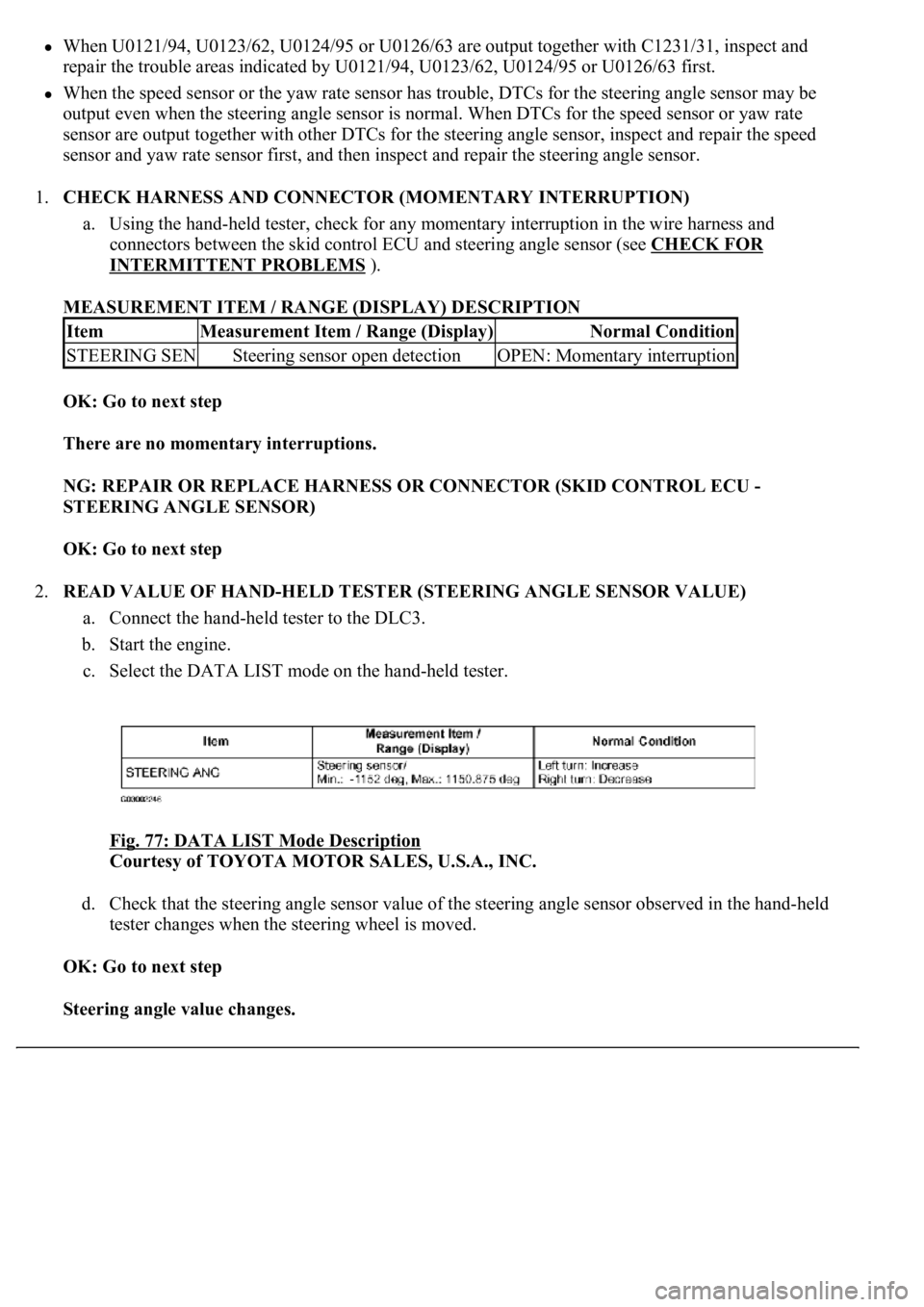
When U0121/94, U0123/62, U0124/95 or U0126/63 are output together with C1231/31, inspect and
repair the trouble areas indicated by U0121/94, U0123/62, U0124/95 or U0126/63 first.
When the speed sensor or the yaw rate sensor has trouble, DTCs for the steering angle sensor may be
output even when the steering angle sensor is normal. When DTCs for the speed sensor or yaw rate
sensor are output together with other DTCs for the steering angle sensor, inspect and repair the speed
sensor and yaw rate sensor first, and then inspect and repair the steering angle sensor.
1.CHECK HARNESS AND CONNECTOR (MOMENTARY INTERRUPTION)
a. Using the hand-held tester, check for any momentary interruption in the wire harness and
connectors between the skid control ECU and steering angle sensor (see CHECK FOR
INTERMITTENT PROBLEMS ).
MEASUREMENT ITEM / RANGE (DISPLAY) DESCRIPTION
OK: Go to next step
There are no momentary interruptions.
NG: REPAIR OR REPLACE HARNESS OR CONNECTOR (SKID CONTROL ECU -
STEERING ANGLE SENSOR)
OK: Go to next step
2.READ VALUE OF HAND-HELD TESTER (STEERING ANGLE SENSOR VALUE)
a. Connect the hand-held tester to the DLC3.
b. Start the engine.
c. Select the DATA LIST mode on the hand-held tester.
Fig. 77: DATA LIST Mode Description
Courtesy of TOYOTA MOTOR SALES, U.S.A., INC.
d. Check that the steering angle sensor value of the steering angle sensor observed in the hand-held
tester changes when the steering wheel is moved.
OK: Go to next step
Steering angle value changes.
ItemMeasurement Item / Range (Display)Normal Condition
STEERING SENSteering sensor open detectionOPEN: Momentary interruption
Page 116 of 4500

CIRCUIT DESCRIPTION
The speed sensor detects wheel speed and sends the appropriate signals to the ECU. These signals are used to
control the ABS control system. The front and rear rotors have 48 serrations each.
When the rotors rotate, the magnetic field emitted by the permanent magnet in the speed sensor generates an
AC voltage. Since the frequency of this AC voltage changes in direct proportion to the speed of the rotor, the
frequenc
y is used by the ECU to detect the speed of each wheel.
Page 495 of 4500

Fig. 17: Diagnostic Trouble Code Information Chart (2 Of 2)
Courtesy of TOYOTA MOTOR SALES, U.S.A., INC.
*1: For codes in the "Indicator Light" column with a "circ" mark, the absorber control indicator lamp blinks at 1
second intervals.
*2: For codes in the "Indicator Light" column with a " (xcirc)" mark, when trouble occurs, "HEIGHT HI" is
displayed on the multi-information display. Also, the master warning light is lit on the combination meter and
an alarm sounds.
*3: Since the relief pressure of the compressed air is 980 kPa (10 kgf/cm
2 , 142 psi), if vehicle height control is
attempted on a steeply sloping road, when the vehicle is overloaded, or when the vehicle height is jacked up
with the engine running, code "C1751" may be output and vehicle height control may be suspended. (This is not
abnormal.) In this case, however, when detecting the first error, approximately 10 minutes after the ignition
switch was turned to the ON position, vehicle height control is resumed. When the following errors are
detected, it takes 70 minutes until the control is resumed.
*4: If vehicle height control is operated while the wheels are removed or the vehicle is jacked up, code "C1752"
may be output, but this is not abnormal. When code "C1752" is output, vehicle height control is not carried out.
However, control is resumed if the ignition switch is turned off, then to the ON position again.
CIRCUIT DESCRIPTION
The height control sensor sub-assy controls the resistance value by following changes in vehicle height. The
suspension control ECU detects the change in vehicle height from the transformed voltage. The suspension
control ECU outputs a constant voltage of 5 V to the SHB terminal of the height control sensor sub-assy.
In the height control sensor, the voltage is changed due to resistance. The changed voltage is output from the
Page 609 of 4500

b. Turn the ignition switch to the ON position and turn the hand-held tester main switch on.
c. Select the item below in the DATA LIST and read its value displayed on the hand-held tester.
AIR SUS:
Fig. 125: Data List Value Description
Courtesy of TOYOTA MOTOR SALES, U.S.A., INC.
d. Check that the steering wheel turning angle value of the steering angle position sensor displayed on
the hand-held tester changes when turning the steering wheel.
Standard:
Steering wheel turning angle value changes.
NG: Go to step 2
OK: REPLACE SUSPENSION CONTROL ECU (SEE REPLACEMENT
)
2.CHECK DIAGNOSTIC CODE OUTPUT
a. Check if the normal system code is output in the CAN communication system (SEE
SUSPENSION CONTROL ECU COMMUNICATION STOP MODE
).
OK:
No DTC is output in the CAN communication system.
NG: REPAIR CIRCUIT INDICATED BY OUTPUT CODE
OK:Go to next step
3.CHECK HARNESS AND CONNECTOR (STEERING SENSOR POWER SOURCE)
a. Disconnect the steering sensor S16 connector.
b. Turn the ignition switch to the ON position.
c. Measure the voltage according to the value (s) in the table below.
TESTER CONNECTION STANDARD SPECIFIED CONDITION
NG: REPAIR OR REPLACE HARNESS OR CONNECTOR
Tester ConnectionSpecified Condition
S16-1 (IG1) - S16-2 (ESS)10 to 14 V
S16-3 (BAT) - S16-2 (ESS)10 to 14 V
Page 2046 of 4500

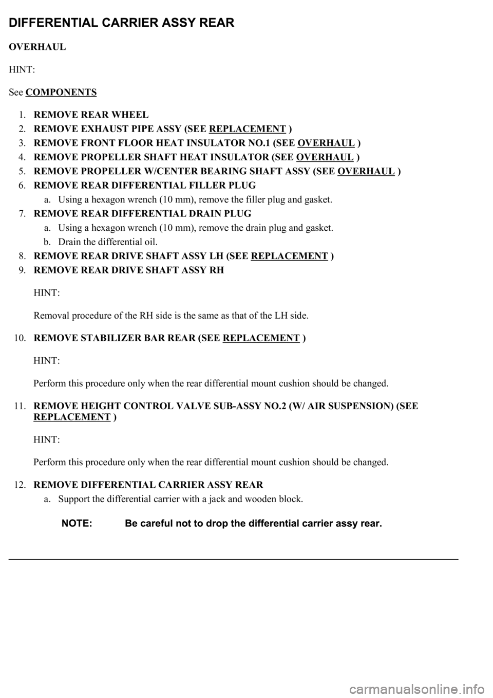
OVERHAUL
HINT:
See COMPONENTS
1.REMOVE REAR WHEEL
2.REMOVE EXHAUST PIPE ASSY (SEE REPLACEMENT
)
3.REMOVE FRONT FLOOR HEAT INSULATOR NO.1 (SEE OVERHAUL
)
4.REMOVE PROPELLER SHAFT HEAT INSULATOR (SEE OVERHAUL
)
5.REMOVE PROPELLER W/CENTER BEARING SHAFT ASSY (SEE OVERHAUL
)
6.REMOVE REAR DIFFERENTIAL FILLER PLUG
a. Using a hexagon wrench (10 mm), remove the filler plug and gasket.
7.REMOVE REAR DIFFERENTIAL DRAIN PLUG
a. Using a hexagon wrench (10 mm), remove the drain plug and gasket.
b. Drain the differential oil.
8.REMOVE REAR DRIVE SHAFT ASSY LH (SEE REPLACEMENT
)
9.REMOVE REAR DRIVE SHAFT ASSY RH
HINT:
Removal procedure of the RH side is the same as that of the LH side.
10.REMOVE STABILIZER BAR REAR (SEE REPLACEMENT
)
HINT:
Perform this procedure only when the rear differential mount cushion should be changed.
11.REMOVE HEIGHT CONTROL VALVE SUB-ASSY NO.2 (W/ AIR SUSPENSION) (SEE
REPLACEMENT
)
HINT:
Perform this procedure only when the rear differential mount cushion should be changed.
12.REMOVE DIFFERENTIAL CARRIER ASSY REAR
a. Support the differential carrier with a jack and wooden block.