Page 2715 of 4500

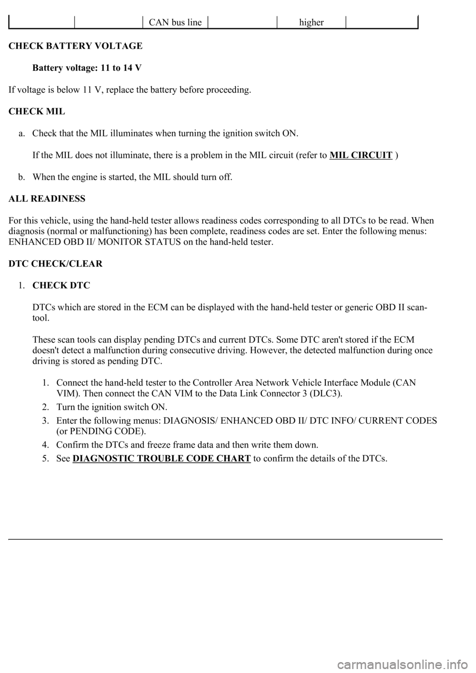
CHECK BATTERY VOLTAGE
Battery voltage: 11 to 14 V
If voltage is below 11 V, replace the battery before proceeding.
CHECK MIL
a. Check that the MIL illuminates when turning the ignition switch ON.
If the MIL does not illuminate, there is a problem in the MIL circuit (refer to MIL CIRCUIT
)
b. When the engine is started, the MIL should turn off.
ALL READINESS
For this vehicle, using the hand-held tester allows readiness codes corresponding to all DTCs to be read. When
diagnosis (normal or malfunctioning) has been complete, readiness codes are set. Enter the following menus:
ENHANCED OBD II/ MONITOR STATUS on the hand-held tester.
DTC CHECK/CLEAR
1.CHECK DTC
DTCs which are stored in the ECM can be displayed with the hand-held tester or generic OBD II scan-
tool.
These scan tools can display pending DTCs and current DTCs. Some DTC aren't stored if the ECM
doesn't detect a malfunction during consecutive driving. However, the detected malfunction during once
driving is stored as pending DTC.
1. Connect the hand-held tester to the Controller Area Network Vehicle Interface Module (CAN
VIM). Then connect the CAN VIM to the Data Link Connector 3 (DLC3).
2. Turn the ignition switch ON.
3. Enter the following menus: DIAGNOSIS/ ENHANCED OBD II/ DTC INFO/ CURRENT CODES
(or PENDING CODE).
4. Confirm the DTCs and freeze frame data and then write them down.
5. See DIAGNOSTIC TROUBLE CODE CHART
to confirm the details of the DTCs.
CAN bus linehigher
Page 2799 of 4500

c. Start the engine and warm it up.
d. Measure the line pressure with SST.
e. Turn the hand - held tester ON.
f. Enter the following menus: DIAGNOSIS / ENHANCED OBD II / ACTIVE TEST.
g. Follow the instructions on the tester and perform the ACTIVE TEST.
h. Measure the line pressure with SST.
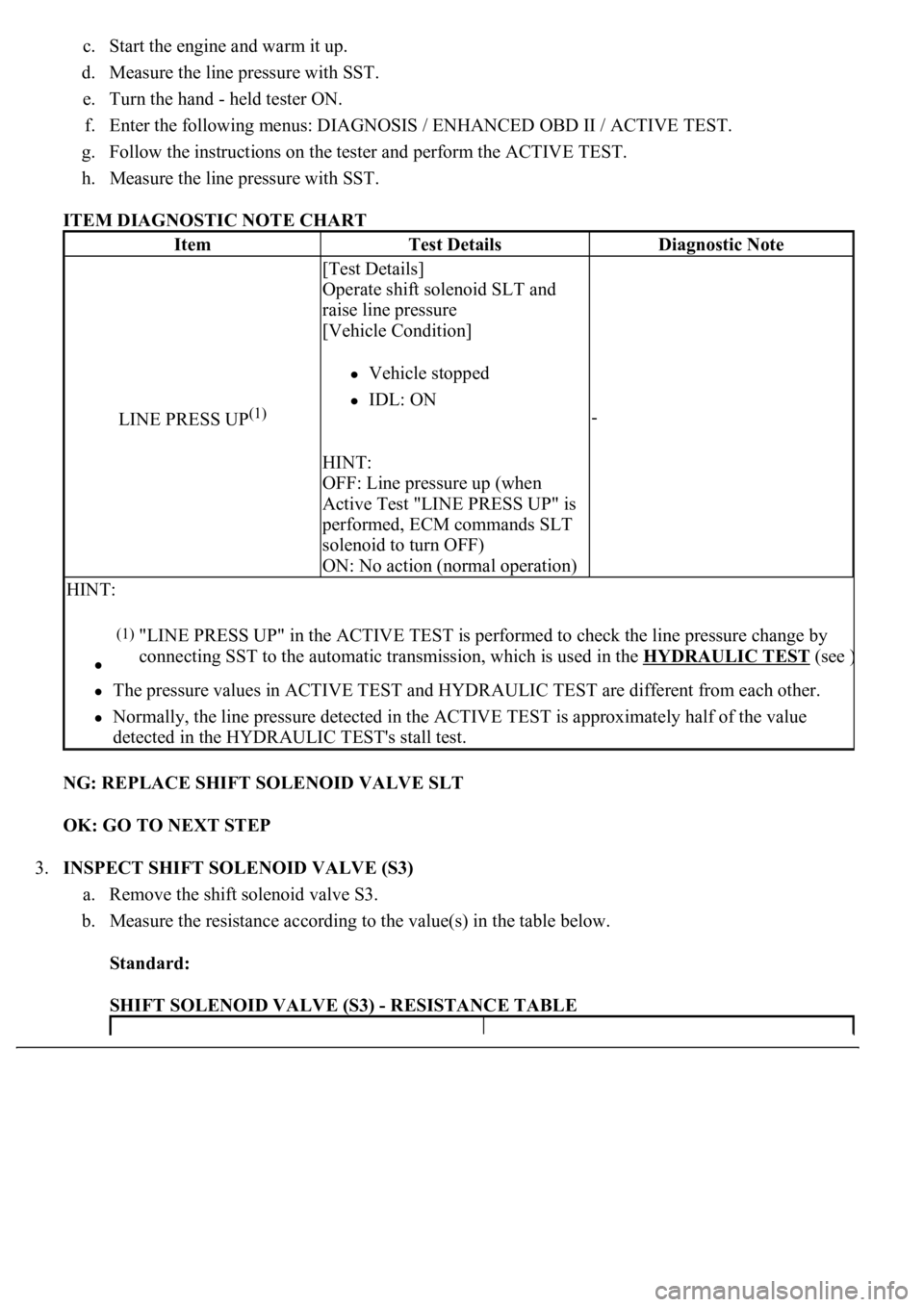
ITEM DIAGNOSTIC NOTE CHART
NG: REPLACE SHIFT SOLENOID VALVE SLT
OK: GO TO NEXT STEP
3.INSPECT SHIFT SOLENOID VALVE (S3)
a. Remove the shift solenoid valve S3.
b. Measure the resistance according to the value(s) in the table below.
Standard:
SHIFT SOLENOID VALVE (S3) - RESISTANCE TABLE
ItemTest DetailsDiagnostic Note
LINE PRESS UP(1)
[Test Details]
Operate shift solenoid SLT and
raise line pressure
[Vehicle Condition]
Vehicle stopped
IDL: ON
HINT:
OFF: Line pressure up (when
Active Test "LINE PRESS UP" is
performed, ECM commands SLT
solenoid to turn OFF)
ON: No action (normal operation)
-
HINT:
The pressure values in ACTIVE TEST and HYDRAULIC TEST are different from each other.
Normally, the line pressure detected in the ACTIVE TEST is approximately half of the value
detected in the HYDRAULIC TEST's stall test.
(1)"LINE PRESS UP" in the ACTIVE TEST is performed to check the line pressure change by
connecting SST to the automatic transmission, which is used in the HYDRAULIC TEST
(see )
Page 2806 of 4500

HINT:
If any other codes besides "P0766" are output, perform troubleshooting for those DTCs first.
B: GO TO RELEVANT DTC CHART (See DIAGNOSTIC TROUBLE CODE CHART
)
A: Go to next step
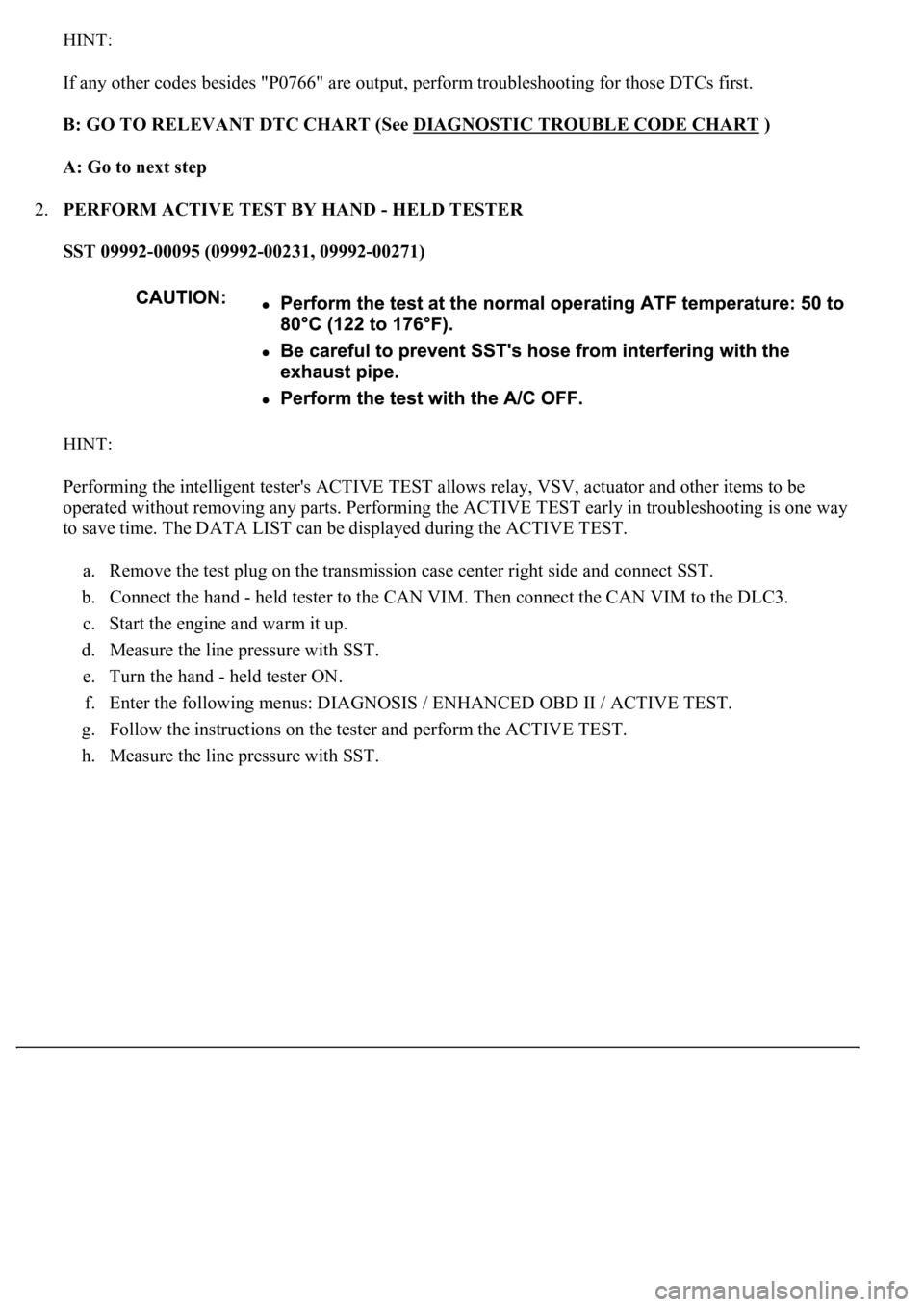
2.PERFORM ACTIVE TEST BY HAND - HELD TESTER
SST 09992-00095 (09992-00231, 09992-00271)
HINT:
Performing the intelligent tester's ACTIVE TEST allows relay, VSV, actuator and other items to be
operated without removing any parts. Performing the ACTIVE TEST early in troubleshooting is one way
to save time. The DATA LIST can be displayed during the ACTIVE TEST.
a. Remove the test plug on the transmission case center right side and connect SST.
b. Connect the hand - held tester to the CAN VIM. Then connect the CAN VIM to the DLC3.
c. Start the engine and warm it up.
d. Measure the line pressure with SST.
e. Turn the hand - held tester ON.
f. Enter the following menus: DIAGNOSIS / ENHANCED OBD II / ACTIVE TEST.
g. Follow the instructions on the tester and perform the ACTIVE TEST.
h. Measure the line pressure with SST.
Page 4453 of 4500
HINT:
<0037004b004c00560003005000520047004800030046004b00480046004e005600030057004b0048000300460052004f0052005500030047004c00560053004f0044005c00030052005100030057004b0048000300500058004f0057004c00100047004c00
560053004f0044005c001100030003[
Illustrations may differ from the actual vehicle depending on the device settings and options. Therefore,
some detailed areas may not be shown exactly the same as on the actual vehicle.
1.Enter diagnostic mode (see DIAGNOSTIC START
-UP/FINISH ).
Fig. 12: Display Diagnostic Menu
Courtesy of TOYOTA MOTOR SALES, U.S.A., INC.
2.Select "Display Check" from the "Diagnosis MENU" screen.
Page 4456 of 4500
4.Select a color bar from the "Color Bar Check Mode" screen.
HINT:
The entire screen turns to the color or stripe selected.
Touching the display will return to the "Color Bar Check" screen.
HINT:
This mode checks the touch switch operation condition on the multi-display.
Illustrations may differ from the actual vehicle depending on the device settings and options. Therefore,
some detailed areas may not be shown exactly the same as on the actual vehicle.
1.Enter diagnostic mode (see DIAGNOSTIC START
-UP/FINISH ).
Fig. 15: Displaying Diagnosis Menu
Courtesy of TOYOTA MOTOR SALES, U.S.A., INC.
2.Select "Display Check" from the "Diagnosis MENU" screen.
Page 4462 of 4500
1.Enter diagnostic mode (see DIAGNOSTIC START-UP/FINISH ).
Fig. 22: Displaying Diagnostic Menu
Courtesy of TOYOTA MOTOR SALES, U.S.A., INC.
2.Select "Display Check" from the "Diagnosis MENU" screen.
Page 4465 of 4500
Fig. 25: Displaying Diagnostic Menu
Courtesy of TOYOTA MOTOR SALES, U.S.A., INC.
2.Select "Navigation Check" from the "Diagnosis MENU" screen.
Page 4468 of 4500
Fig. 28: Displaying Diagnostic Chart
Courtesy of TOYOTA MOTOR SALES, U.S.A., INC.
2.Select "Navigation Check" from the "Diagnosis MENU" screen.