Page 2 of 4500
Fluid SpecificationsSee FLUIDS under MAINTENANCE tab.
Flywheel/Flex Plate
(Drive Plate) TorqueStep1: 49 N.m (500 kgf.cm, 36 ft lbs)
Step2: Turn 90°
Fuel System
Pressure
Specification304 to 343 kPa (3.1 to 3.5 kgf/cm2 , 44 to 50 psi)
Fuel Pressure Test
ProcedureON-VEHICLE INSPECTION
Fuel Filter
LocationCOMPONENTS
Ignition
Firing Order &
Cylinder
IdentificationFIRING ORDER & CYLINDER IDENTIFICATION
Spark Plug
TypeND SK20R11
NGK 1FR6A11
GapStandard electrode gap: 1.0 - 1.1 mm (0.039 - 0.043 in.)
Maximum electrode gap: 1.3 mm (0.051 in.)
Torque7.5 N.m (76 kgf.cm, 66 ft.lbf)
Starting
StarterSERVICE DATA
TorqueTORQUE SPECIFICATION
Wheel Alignment
Front
Adjustment
SpecificationsSERVICE DATA
TorqueTORQUE SPECIFICATION
Rear
Adjustment
SpecificationsSERVICE DATA
TorqueTORQUE SPECIFICATION
Wheel & Tire
Wheel Lug Nut
Torque103 N.m (1,050 kgf.cm 76 ft.lbf)
Page 2635 of 4500

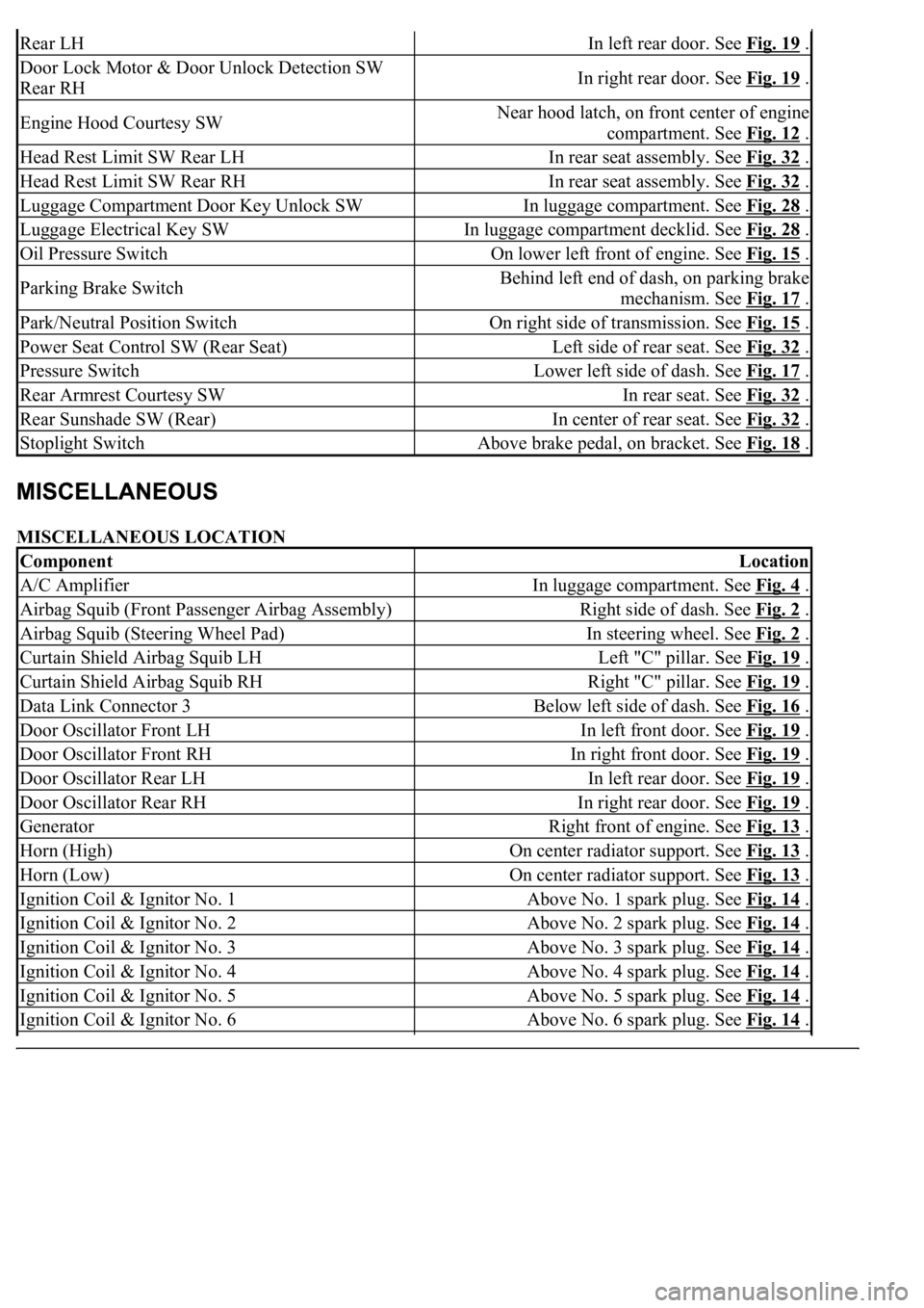
MISCELLANEOUS LOCATION
Rear LHIn left rear door. See Fig. 19 .
Door Lock Motor & Door Unlock Detection SW
Rear RHIn right rear door. See Fig. 19 .
Engine Hood Courtesy SWNear hood latch, on front center of engine
compartment. See Fig. 12
.
Head Rest Limit SW Rear LHIn rear seat assembly. See Fig. 32 .
Head Rest Limit SW Rear RHIn rear seat assembly. See Fig. 32 .
Luggage Compartment Door Key Unlock SWIn luggage compartment. See Fig. 28 .
Luggage Electrical Key SWIn luggage compartment decklid. See Fig. 28 .
Oil Pressure SwitchOn lower left front of engine. See Fig. 15 .
Parking Brake SwitchBehind left end of dash, on parking brake
mechanism. See Fig. 17
.
Park/Neutral Position SwitchOn right side of transmission. See Fig. 15 .
Power Seat Control SW (Rear Seat)Left side of rear seat. See Fig. 32 .
Pressure SwitchLower left side of dash. See Fig. 17 .
Rear Armrest Courtesy SWIn rear seat. See Fig. 32 .
Rear Sunshade SW (Rear)In center of rear seat. See Fig. 32 .
Stoplight SwitchAbove brake pedal, on bracket. See Fig. 18 .
ComponentLocation
A/C AmplifierIn luggage compartment. See Fig. 4 .
Airbag Squib (Front Passenger Airbag Assembly)Right side of dash. See Fig. 2 .
Airbag Squib (Steering Wheel Pad)In steering wheel. See Fig. 2 .
Curtain Shield Airbag Squib LHLeft "C" pillar. See Fig. 19 .
Curtain Shield Airbag Squib RHRight "C" pillar. See Fig. 19 .
Data Link Connector 3Below left side of dash. See Fig. 16 .
Door Oscillator Front LHIn left front door. See Fig. 19 .
Door Oscillator Front RHIn right front door. See Fig. 19 .
Door Oscillator Rear LHIn left rear door. See Fig. 19 .
Door Oscillator Rear RHIn right rear door. See Fig. 19 .
GeneratorRight front of engine. See Fig. 13 .
Horn (High)On center radiator support. See Fig. 13 .
Horn (Low)On center radiator support. See Fig. 13 .
Ignition Coil & Ignitor No. 1Above No. 1 spark plug. See Fig. 14 .
Ignition Coil & Ignitor No. 2Above No. 2 spark plug. See Fig. 14 .
Ignition Coil & Ignitor No. 3Above No. 3 spark plug. See Fig. 14 .
Ignition Coil & Ignitor No. 4Above No. 4 spark plug. See Fig. 14 .
Ignition Coil & Ignitor No. 5Above No. 5 spark plug. See Fig. 14 .
Ignition Coil & Ignitor No. 6Above No. 6 spark plug. See Fig. 14 .
Page 2636 of 4500

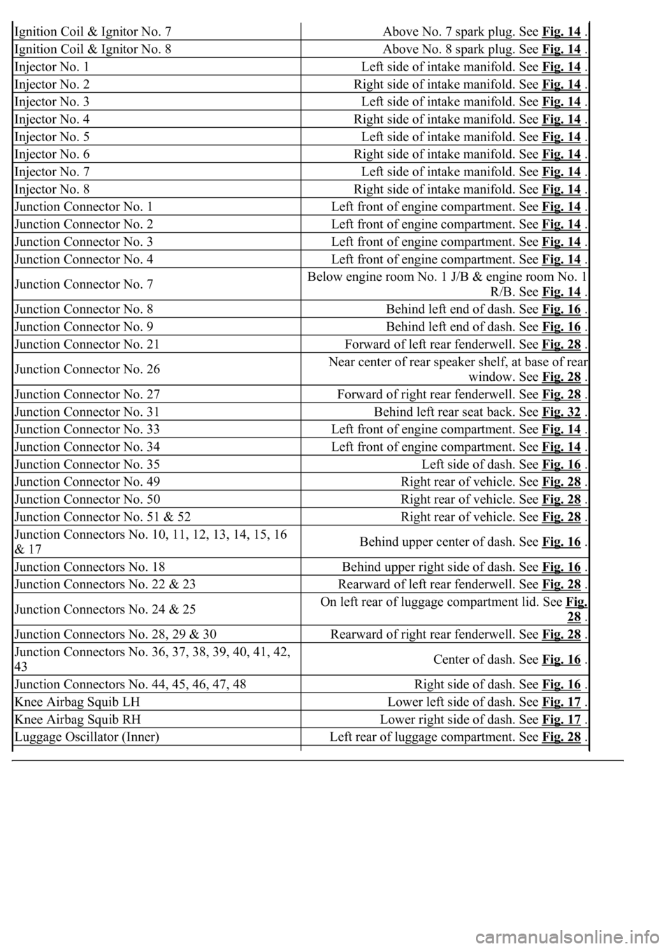
Ignition Coil & Ignitor No. 7Above No. 7 spark plug. See Fig. 14 .
Ignition Coil & Ignitor No. 8Above No. 8 spark plug. See Fig. 14 .
Injector No. 1Left side of intake manifold. See Fig. 14 .
Injector No. 2Right side of intake manifold. See Fig. 14 .
Injector No. 3Left side of intake manifold. See Fig. 14 .
Injector No. 4Right side of intake manifold. See Fig. 14 .
Injector No. 5Left side of intake manifold. See Fig. 14 .
Injector No. 6Right side of intake manifold. See Fig. 14 .
Injector No. 7Left side of intake manifold. See Fig. 14 .
Injector No. 8Right side of intake manifold. See Fig. 14 .
Junction Connector No. 1Left front of engine compartment. See Fig. 14 .
Junction Connector No. 2Left front of engine compartment. See Fig. 14 .
Junction Connector No. 3Left front of engine compartment. See Fig. 14 .
Junction Connector No. 4Left front of engine compartment. See Fig. 14 .
Junction Connector No. 7Below engine room No. 1 J/B & engine room No. 1
R/B. See Fig. 14
.
Junction Connector No. 8Behind left end of dash. See Fig. 16 .
Junction Connector No. 9Behind left end of dash. See Fig. 16 .
Junction Connector No. 21Forward of left rear fenderwell. See Fig. 28 .
Junction Connector No. 26Near center of rear speaker shelf, at base of rear
window. See Fig. 28
.
Junction Connector No. 27Forward of right rear fenderwell. See Fig. 28 .
Junction Connector No. 31Behind left rear seat back. See Fig. 32 .
Junction Connector No. 33Left front of engine compartment. See Fig. 14 .
Junction Connector No. 34Left front of engine compartment. See Fig. 14 .
Junction Connector No. 35Left side of dash. See Fig. 16 .
Junction Connector No. 49Right rear of vehicle. See Fig. 28 .
Junction Connector No. 50Right rear of vehicle. See Fig. 28 .
Junction Connector No. 51 & 52Right rear of vehicle. See Fig. 28 .
<002d0058005100460057004c00520051000300260052005100510048004600570052005500560003003100520011000300140013000f000300140014000f000300140015000f000300140016000f000300140017000f000300140018000f00030014001900
03[
& 17Behind upper center of dash. See Fig. 16 .
Junction Connectors No. 18Behind upper right side of dash. See Fig. 16 .
Junction Connectors No. 22 & 23Rearward of left rear fenderwell. See Fig. 28 .
Junction Connectors No. 24 & 25On left rear of luggage compartment lid. See Fig.
28 .
Junction Connectors No. 28, 29 & 30Rearward of right rear fenderwell. See Fig. 28 .
<002d0058005100460057004c00520051000300260052005100510048004600570052005500560003003100520011000300160019000f00030016001a000f00030016001b000f00030016001c000f000300170013000f000300170014000f00030017001500
0f0003[
43Center of dash. See Fig. 16 .
Junction Connectors No. 44, 45, 46, 47, 48Right side of dash. See Fig. 16 .
Knee Airbag Squib LHLower left side of dash. See Fig. 17 .
Knee Airbag Squib RHLower right side of dash. See Fig. 17 .
Luggage Oscillator (Inner)Left rear of luggage compartment. See Fig. 28 .
Page 3279 of 4500
INSPECTION
1.INSPECT ENGINE COOLANT (See REPLACEMENT
)
2.INSPECT ENGINE OIL (See ON
-VEHICLE INSPECTION )
3.INSPECT BATTERY (See REPLACEMENT
)
4.INSPECT AIR CLEANER FILTER ELEMENT SUB-ASSY
5.INSPECT SPARK PLUG (See REPLACEMENT
)
6.INSPECT FAN AND GENERATOR V BELT
HINT:
Use of the automatic tensioner has made tension and flexibility measurements unnecessary.
a. Check that the indicator mark on the automatic tensioner is within range A as shown in the
illustration.
b. When the mark is out of the standard range, replace the V belt with a new one.
Page 3284 of 4500
f. Remove the spark plugs.
g. Disconnect the 8 injector connectors.
h. Check the cylinder compression pressure.
SST 09992-00500
1. Insert a compression gauge into the spark plug hole.
2. Fully open the throttle.
3. While cranking the engine, measure the compression pressure.
Compression pressure:
1.2 MPa (12.5 kgf/cm
2 , 178 psi)
Minimum pressure: 981 kPa (10.0 kgf/cm
2 , 142 psi)
Difference between each cylinder:
98 kPa (1.0 kgf/cm
2 , 14 psi)
4. If the cylinder compression is low, pour a small amount of engine oil into the cylinder
throu
gh the spark plug hole and inspect again.
Page 3285 of 4500
Fig. 5: Checking Cylinder'S Compression Pressure
Courtesy of TOYOTA MOTOR SALES, U.S.A., INC.
HINT:
If adding oil increases the compression, the piston rings and/or cylinder bore may be worn or
damaged.
If pressure stays low, a valve may be stuck or seated improperly, or there may be leakage in
the gasket.
i. Connect the 8 injector connectors.
j. Install the spark plugs.
k. Install the 8 ignition coils.
l. Install the oil level gauge guide.
m. Connect the throttle control motor connector.
n. Install the air cleaner inlet and intake air pipe.
o. Install the V-bank cover.
10.INSPECT CO/HC
a. Start the engine.
b. Rev the engine at 2,500 rpm for approximately 180 seconds.
Page 3361 of 4500

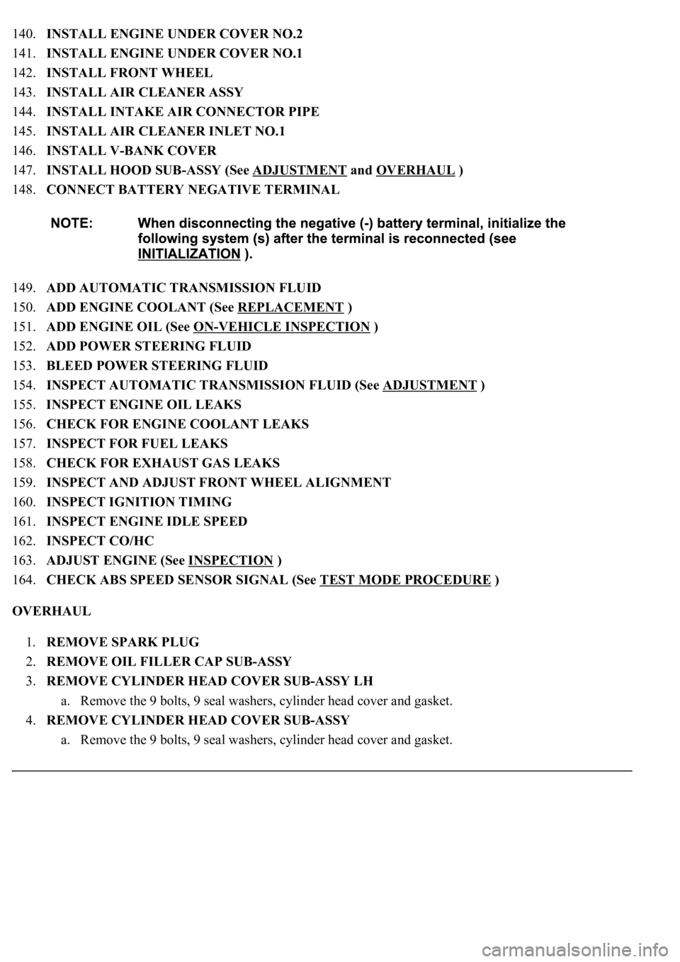
140.INSTALL ENGINE UNDER COVER NO.2
141.INSTALL ENGINE UNDER COVER NO.1
142.INSTALL FRONT WHEEL
143.INSTALL AIR CLEANER ASSY
144.INSTALL INTAKE AIR CONNECTOR PIPE
145.INSTALL AIR CLEANER INLET NO.1
146.INSTALL V-BANK COVER
147.INSTALL HOOD SUB-ASSY (See ADJUSTMENT
and OVERHAUL )
148.CONNECT BATTERY NEGATIVE TERMINAL
149.ADD AUTOMATIC TRANSMISSION FLUID
150.ADD ENGINE COOLANT (See REPLACEMENT
)
151.ADD ENGINE OIL (See ON
-VEHICLE INSPECTION )
152.ADD POWER STEERING FLUID
153.BLEED POWER STEERING FLUID
154.INSPECT AUTOMATIC TRANSMISSION FLUID (See ADJUSTMENT
)
155.INSPECT ENGINE OIL LEAKS
156.CHECK FOR ENGINE COOLANT LEAKS
157.INSPECT FOR FUEL LEAKS
158.CHECK FOR EXHAUST GAS LEAKS
159.INSPECT AND ADJUST FRONT WHEEL ALIGNMENT
160.INSPECT IGNITION TIMING
161.INSPECT ENGINE IDLE SPEED
162.INSPECT CO/HC
163.ADJUST ENGINE (See INSPECTION
)
164.CHECK ABS SPEED SENSOR SIGNAL (See TEST MODE PROCEDURE
)
OVERHAUL
1.REMOVE SPARK PLUG
2.REMOVE OIL FILLER CAP SUB-ASSY
3.REMOVE CYLINDER HEAD COVER SUB-ASSY LH
a. Remove the 9 bolts, 9 seal washers, cylinder head cover and gasket.
4.REMOVE CYLINDER HEAD COVER SUB-ASSY
a. Remove the 9 bolts, 9 seal washers, c
ylinder head cover and gasket.
Page 3392 of 4500
Fig. 111: Removing Engine Rear Oil Seal Retainer Using Screwdriver
Courtesy of TOYOTA MOTOR SALES, U.S.A., INC.
40.REMOVE SPARK PLUG TUBE GASKET
a. Bend the 4 ventilation case claws installed on the cylinder head cover to an angle of 90° or more.
b. Using a screwdriver, pry out the gasket.
HINT:
Tape the screwdriver tip before use.