Page 477 of 4500
Fig. 6: Connecting Hand-Held Tester To DLC3
Courtesy of TOYOTA MOTOR SALES, U.S.A., INC.
TEST MODE
HINT:
In step (6), all signals can be checked together.
Check ItemOperation (A)Operation (B)
Height control switchNORM
positionHIGH position
Absorber control
switch-Slowly move the absorber control switch "NORM"
<--> "SPORT" both ways once
Right front acceleration
sensor-Keep the vehicle still without any vertical
movement for 1 second
Left front acceleration
sensor-Keep the vehicle still without any vertical
movement for 1 second
Rear acceleration
sensor-Keep the vehicle still without any vertical
movement for 1 second
Page 616 of 4500
Fig. 133: Identifying Height Control Switch Connector Terminals
Courtesy of TOYOTA MOTOR SALES, U.S.A., INC.
NG: REPAIR OR REPLACE HARNESS OR CONNECTOR
OK: REPLACE SUSPENSION CONTROL ECU (SEE REPLACEMENT
)
CIRCUIT DESCRIPTION
The absorber control switch is used to select the attenuation modes of the shock absorber. 2 levels of
attenuation, "SPORT" and "NORM", are available.
Page 617 of 4500
Fig. 134: DTC C1787 Detecting Condition And Trouble Area
Courtesy of TOYOTA MOTOR SALES, U.S.A., INC.
HINT:
DTC C1787 is output only in the test mode.
WIRING DIAGRAM
Fig. 135: Absorber Control Switch Wiring Diagram
Courtesy of TOYOTA MOTOR SALES, U.S.A., INC.
INSPECTION PROCEDURE
1.INSPECT ABSORBER CONTROL SWITCH
a. Disconnect the absorber control switch connector.
b. Measure the resistance according to the value (s) in the table below.
TESTER CONNECTION STANDARD SPECIFIED CONDITION
Switch ConditionTester ConnectionSpecified Condition
"SPORT"2 (GND) - 4 (ECU1)Below 1 ohms
"NORM"2 (GND) - 4 (ECU1)10 Kohms or higher
Page 637 of 4500
Fig. 3: Identifying Component Locations (3 Of 3)
Courtesy of TOYOTA MOTOR SALES, U.S.A., INC.
REPLACEMENT
HINT:
See COMPONENTS
See LOCATION
Installation is in the reverse order of removal.
Set to "SHIP" mode to prevent mechanical damage due to any impacts when the radio is transported.
Attach the label shown below to the top of the product case so as not to skip any procedure and to follow
the procedure correctly.
1.SHIP MODE SETTING
a. Take out all CDs.
b. Turn the ignition switch to the OFF position.
c. While holdin
g the "UP" and "DISC" switches, turn the ignition switch to the ACC position.
Page 1744 of 4500

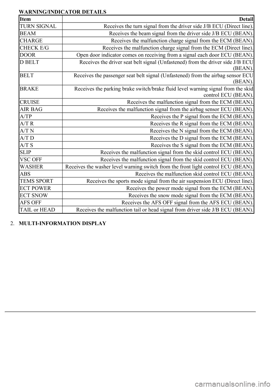
WARNING/INDICATOR DETAILS
2.MULTI-INFORMATION DISPLAY
ItemDetail
TURN SIGNALReceives the turn signal from the driver side J/B ECU (Direct line).
BEAMReceives the beam signal from the driver side J/B ECU (BEAN).
CHARGEReceives the malfunction charge signal from the ECM (BEAN).
CHECK E/GReceives the malfunction charge signal from the ECM (Direct line).
DOOROpen door indicator comes on receiving from a signal each door ECU (BEAN).
D BELTReceives the driver seat belt signal (Unfastened) from the driver side J/B ECU
(BEAN).
BELTReceives the passenger seat belt signal (Unfastened) from the airbag sensor ECU
(BEAN).
BRAKEReceives the parking brake switch/brake fluid level warning signal from the skid
control ECU (BEAN).
CRUISEReceives the malfunction signal from the ECM (BEAN).
AIR BAGReceives the malfunction signal from the airbag sensor ECU (BEAN).
A/TPReceives the P signal from the ECM (BEAN).
A/T RReceives the R signal from the ECM (BEAN).
A/T NReceives the N signal from the ECM (BEAN).
A/T DReceives the D signal from the ECM (BEAN).
A/T SReceives the S signal from the ECM (BEAN).
SLIPReceives the malfunction signal from the skid control ECU (BEAN).
VSC OFFReceives the malfunction signal from the skid control ECU (BEAN).
WASHERReceives the washer level warning switch from the front light control ECU (BEAN).
ABSReceives the malfunction skid control ECU (BEAN).
TEMS SPORTReceives the sports mode signal from the air suspension ECU (Direct line).
ECT POWERReceives the power mode signal from the ECM (BEAN).
ECT SNOWReceives the snow mode signal from the ECM (BEAN).
AFS OFFReceives the AFS OFF signal from the AFS ECU (BEAN).
TAIL or HEADReceives the malfunction tail or head signal from driver side J/B ECU (BEAN).
Page 2030 of 4500
RENAULT
RENAULT - IMPORTED CARS & TRUCKS
ROLLS-ROYCE
ROLLS-ROYCE - IMPORTED CARS & TRUCKS
SAAB
SAAB - IMPORTED CARS & TRUCKS
928STop Front Of Engine
944 SeriesOn Left Side Of Engine Compartment
ApplicationConnector Location
Sportwagon
Engine DiagnosticOn Center Of Firewall
Fuel Injection DiagnosticRight Rear Of Engine Compartment,
Behind Airflow Meter
ApplicationConnector Location
All Models
1996-00In Glove Compartment
2001-Under Left Side Of Dash
ApplicationConnector Location
900 Series
1986-90In Front Of Fuse/Relay Panel
1991-93Under Back Seat, On Right Side
1994
ConvertibleUnder Rear Seat
HatchbackUnder Steering Column
All OthersUnder Right Front Seat