Page 1 of 4500
LS430 SPECIFICATIONS INDEX
SystemSpecification/Procedure
Air Conditioning
ServiceSERVICE DATA
TorqueTORQUE SPECIFICATION
Axle Nut/Hub Nut
Front69 N.m (700 kgf.cm, 51 ft.lbf)
Rear290 N.m (2,960 kgf.cm, 214 ft.lbf)
BatteryNA
Brakes
Bleeding
SequenceBLEEDING
Disc BrakesSERVICE DATA
TorqueTORQUE SPECIFICATION
Charging
GeneratorSERVICE DATA
TorqueTORQUE SPECIFICATION
Drive Belts
AdjustmentREPLACEMENT
Belt RoutingDRIVE BELT
Engine Cooling
General Service
SpecificationsSERVICE DATA
Radiator Cap
PressureStandard Value
93 to 123 kPa (0.95 to 1.25 kgf/cm
2 , 13.5 to 17.8 psi)
Minimum Standard Value
78 kPa (0.8 kgf/cm
2 , 11.4 psi)
Thermostat R & ITHERMOSTAT
Water Pump R &
IWATER PUMP
Engine Mechanical
CompressionSERVICE DATA
Oil Pressureat idle, 29 kPa (0.3 kgf.cm2 , 43 psi) or more
at 3,000 rpm, 294 to 588 kPa (3.0 to 6.0 kgf.cm
2 , 43 to 85 psi)
OverhaulSERVICE DATA
TorqueTORQUE SPECIFICATION
Page 125 of 4500
OK: Go to next step
2.INSPECT BATTERY
a. Check the battery voltage.
Standard:
Voltage: 10 to 14 V
NG: INSPECT CHARGING SYSTEM (SEE ON
-VEHICLE INSPECTION )
OK: Go to next step
3.INSPECT SKID CONTROL ECU TERMINAL VOLTAGE (IG1 TERMINAL)
a. Connect the hand-held tester to the DLC3.
b. Start the engine.
c. Select the DATA LIST mode on the hand-held tester.
Fig. 91: DATA LIST Mode Description
Courtesy of TOYOTA MOTOR SALES, U.S.A., INC.
d. Read the voltage condition output from the ECU displayed on the hand-held tester.
Standard:
"Normal" is displayed.
NG: Go to step 4
OK: REPLACE ABS & TRACTION ACTUATOR ASSY (SEE REPLACEMENT
)
4.INSPECT SKID CONTROL ECU CONNECTOR (GND TERMINAL CONTINUITY)
a. Disconnect the skid control ECU connector.
b. Measure the resistance according to the value (s) in the table below.
Standard:
Page 150 of 4500
INSPECTION PROCEDURE
1.CHECK DTC
a. Is DTC output for ABS, CAN and/or MPX?
OK: Go to next step
DTC OUTPUT DESCRIPTION
B: REPAIR CIRCUIT INDICATED BY OUTPUT CODE
A: Go to next step
2.INSPECT SKID CONTROL ECU CONNECTOR (SEE REPLACEMENT
)
a. Check the ECU connectors connecting condition.
OK: Go to next step
The connector is securely connected.
NG: CONNECT CONNECTOR TO ECU CORRECTLY
OK: Go to next step
3.INSPECT BATTERY
a. Check the battery voltage.
Standard:
Voltage: 10 to 14 V
NG: INSPECT CHARGING SYSTEM (SEE ON
-VEHICLE INSPECTION )
OK: Go to next step
4.INSPECT SKID CONTROL ECU TERMINAL VOLTAGE (IG1 TERMINAL)
a. Connect the hand-held tester to the DLC3.
b. Start the engine.
c. Select the DATA LIST mode on the han
d-held tester.
DTC is not outputA
DTC is outputB
Page 157 of 4500
Standard:
DTC OUTPUT DESCRIPTION
B: REPAIR CIRCUIT INDICATED BY OUTPUT DTC
A: Go to next step
2.INSPECT SKID CONTROL ECU CONNECTOR (SEE REPLACEMENT
)
a. Check the ECU connector's connecting condition.
OK: Go to next step
The connector is securely connected.
NG: CONNECT CONNECTOR TO ECU CORRECTLY
OK: Go to next step
3.INSPECT BATTERY
a. Check the battery voltage.
Standard:
Voltage: 10 to 14 V
NG: INSPECT CHARGING SYSTEM (SEE ON
-VEHICLE INSPECTION )
OK: Go to next step
4.INSPECT SKID CONTROL ECU TERMINAL VOLTAGE (IG1 TERMINAL)
a. Connect the hand-held tester to the DLC3.
b. Start the engine.
c. Select the DATA LIST mode on the hand-held tester.
Fig. 117: Item Measurement Item /Range Normal Condition
Courtesy of TOYOTA MOTOR SALES, U.S.A., INC.
DTC is not outputA
DTC is outputB
Page 469 of 4500

If the vehicle is raised with its engine running, connect terminals OPB and CG of the DLC3 to stop
the vehicle height control operation of the suspension control ECU.
Do not operate the steering wheel if there is no air in the pneumatic cylinder.
HINT:
The pneumatic cylinder could be damaged if twisted without air in the cylinder.
In the case of lifting down the vehicle without air in the cylinder, make sure all the pipes are securely
connected.
HINT:
The pneumatic cylinder could be damaged if any pipe is disconnected while lifting down the vehicle.
Do not apply battery voltage to the compressor motor for more than 60 seconds to prevent damage to the
motor.
HINT:
When it is necessary to perform the operation by charging the battery for more than 60 seconds, for example
height recovery without air in the cylinder, proceed to the operation as follows: after 60 seconds have passed,
turn the ignition switch off once, and then turn the ignition switch to the ON position again for commencement
of operation.
Page 4162 of 4500
Fig. 2: Identifying Engine Room No. 1 Junction & Relay Block Components
Courtesy of TOYOTA MOTOR SALES, U.S.A., INC.
Engine Room No. 1 Junction & Relay Block Fuses
FuseSystem
7.5AA/C IGAutomatic Air Conditioning (Front)
7.5AEFI NO.2Engine Control
7.5AFR IGABS
Automatic Air Conditioning (Front)
Back-Up Light
Charging
Clock (w/ LEXUS Navigation System)
Cruise Control
Door Closer (w/ Smart Key System)
Door Closer (w/o Smart Key System)
Door Lock Control (w/ Smart Key System)
Door Lock Control (w/o Smart Key System)
Page 4166 of 4500

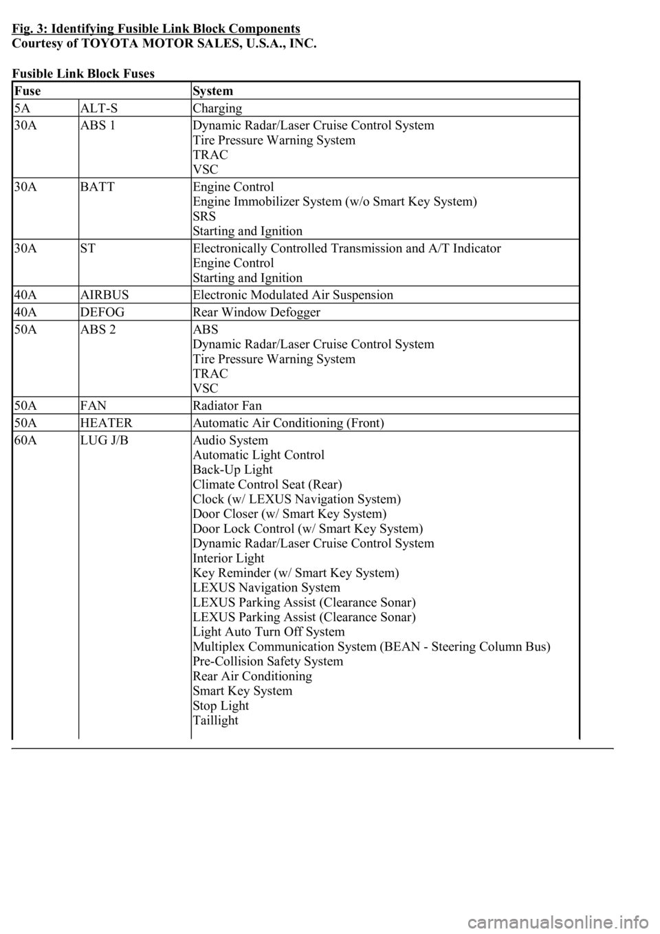
Fig. 3: Identifying Fusible Link Block Components
Courtesy of TOYOTA MOTOR SALES, U.S.A., INC.
Fusible Link Block Fuses
FuseSystem
5AALT-SCharging
30AABS 1Dynamic Radar/Laser Cruise Control System
Tire Pressure Warning System
TRAC
VSC
30ABATTEngine Control
Engine Immobilizer System (w/o Smart Key System)
SRS
Starting and Ignition
30ASTElectronically Controlled Transmission and A/T Indicator
Engine Control
Starting and Ignition
40AAIRBUSElectronic Modulated Air Suspension
40ADEFOGRear Window Defogger
50AABS 2ABS
Dynamic Radar/Laser Cruise Control System
Tire Pressure Warning System
TRAC
VSC
50AFANRadiator Fan
50AHEATERAutomatic Air Conditioning (Front)
60ALUG J/BAudio System
Automatic Light Control
Back-Up Light
Climate Control Seat (Rear)
Clock (w/ LEXUS Navigation System)
Door Closer (w/ Smart Key System)
Door Lock Control (w/ Smart Key System)
Dynamic Radar/Laser Cruise Control System
Interior Light
Key Reminder (w/ Smart Key System)
LEXUS Navigation System
LEXUS Parking Assist (Clearance Sonar)
LEXUS Parking Assist (Clearance Sonar)
Light Auto Turn Off System
Multiplex Communication System (BEAN - Steering Column Bus)
Pre-Collision Safety System
Rear Air Conditioning
Smart Key System
Stop Light
Taillight
Page 4167 of 4500
DRIVER SIDE JUNCTION BLOCK
Fig. 4: Locating Instrument Panel Junction & Relay Blocks
Courtesy of TOYOTA MOTOR SALES, U.S.A., INC.
Theft Deterrent (w/ Smart Key System)
Wireless Door Lock Control (w/ Smart Key System)
140AALTABS
Charging
Multiplex Communication System (BEAN - Steering Column Bus)
Tire Pressure Warning System
TRAC
VSC