2003 LEXUS LS430 Intake manifold
[x] Cancel search: Intake manifoldPage 2018 of 4500
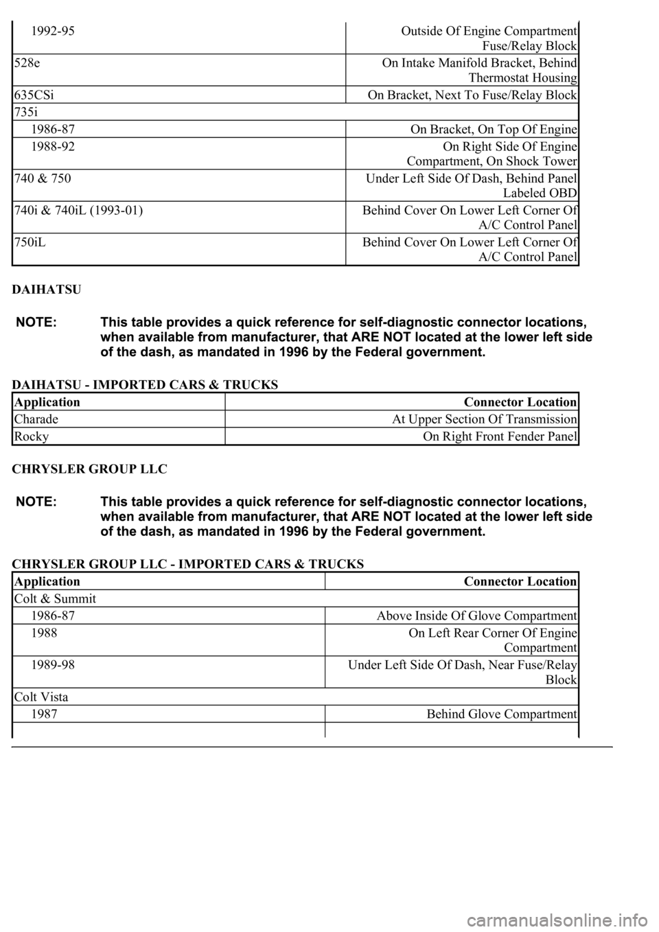
DAIHATSU
DAIHATSU - IMPORTED CARS & TRUCKS
CHRYSLER GROUP LLC
CHRYSLER GROUP LLC - IMPORTED CARS & TRUCKS
1992-95Outside Of Engine Compartment
Fuse/Relay Block
528eOn Intake Manifold Bracket, Behind
Thermostat Housing
635CSiOn Bracket, Next To Fuse/Relay Block
735i
1986-87On Bracket, On Top Of Engine
1988-92On Right Side Of Engine
Compartment, On Shock Tower
740 & 750Under Left Side Of Dash, Behind Panel
Labeled OBD
740i & 740iL (1993-01)Behind Cover On Lower Left Corner Of
A/C Control Panel
750iLBehind Cover On Lower Left Corner Of
A/C Control Panel
ApplicationConnector Location
CharadeAt Upper Section Of Transmission
RockyOn Right Front Fender Panel
ApplicationConnector Location
Colt & Summit
1986-87Above Inside Of Glove Compartment
1988On Left Rear Corner Of Engine
Compartment
1989-98Under Left Side Of Dash, Near Fuse/Relay
Block
Colt Vista
1987Behind Glove Compartment
Page 2636 of 4500
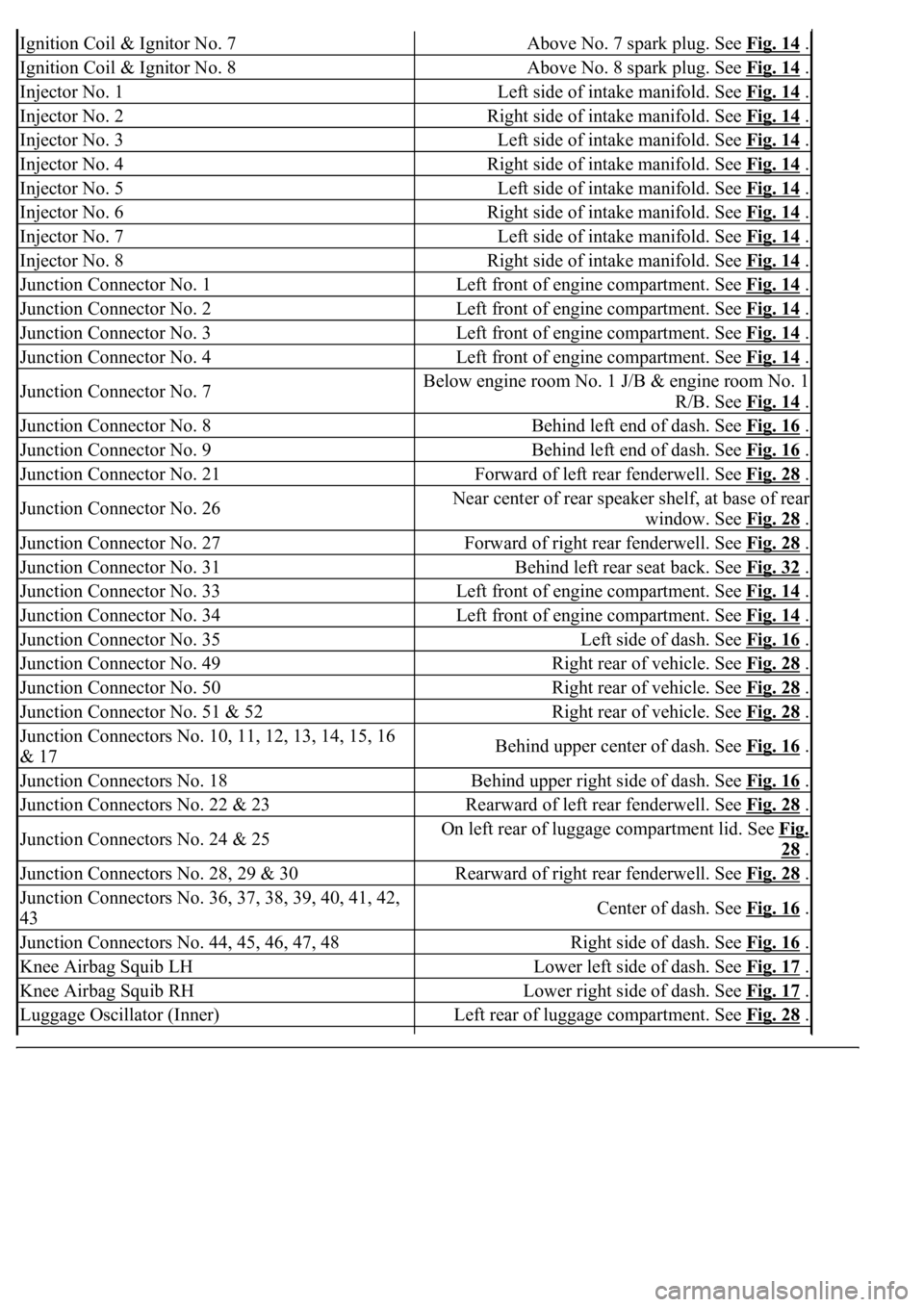
Ignition Coil & Ignitor No. 7Above No. 7 spark plug. See Fig. 14 .
Ignition Coil & Ignitor No. 8Above No. 8 spark plug. See Fig. 14 .
Injector No. 1Left side of intake manifold. See Fig. 14 .
Injector No. 2Right side of intake manifold. See Fig. 14 .
Injector No. 3Left side of intake manifold. See Fig. 14 .
Injector No. 4Right side of intake manifold. See Fig. 14 .
Injector No. 5Left side of intake manifold. See Fig. 14 .
Injector No. 6Right side of intake manifold. See Fig. 14 .
Injector No. 7Left side of intake manifold. See Fig. 14 .
Injector No. 8Right side of intake manifold. See Fig. 14 .
Junction Connector No. 1Left front of engine compartment. See Fig. 14 .
Junction Connector No. 2Left front of engine compartment. See Fig. 14 .
Junction Connector No. 3Left front of engine compartment. See Fig. 14 .
Junction Connector No. 4Left front of engine compartment. See Fig. 14 .
Junction Connector No. 7Below engine room No. 1 J/B & engine room No. 1
R/B. See Fig. 14
.
Junction Connector No. 8Behind left end of dash. See Fig. 16 .
Junction Connector No. 9Behind left end of dash. See Fig. 16 .
Junction Connector No. 21Forward of left rear fenderwell. See Fig. 28 .
Junction Connector No. 26Near center of rear speaker shelf, at base of rear
window. See Fig. 28
.
Junction Connector No. 27Forward of right rear fenderwell. See Fig. 28 .
Junction Connector No. 31Behind left rear seat back. See Fig. 32 .
Junction Connector No. 33Left front of engine compartment. See Fig. 14 .
Junction Connector No. 34Left front of engine compartment. See Fig. 14 .
Junction Connector No. 35Left side of dash. See Fig. 16 .
Junction Connector No. 49Right rear of vehicle. See Fig. 28 .
Junction Connector No. 50Right rear of vehicle. See Fig. 28 .
Junction Connector No. 51 & 52Right rear of vehicle. See Fig. 28 .
<002d0058005100460057004c00520051000300260052005100510048004600570052005500560003003100520011000300140013000f000300140014000f000300140015000f000300140016000f000300140017000f000300140018000f00030014001900
03[
& 17Behind upper center of dash. See Fig. 16 .
Junction Connectors No. 18Behind upper right side of dash. See Fig. 16 .
Junction Connectors No. 22 & 23Rearward of left rear fenderwell. See Fig. 28 .
Junction Connectors No. 24 & 25On left rear of luggage compartment lid. See Fig.
28 .
Junction Connectors No. 28, 29 & 30Rearward of right rear fenderwell. See Fig. 28 .
<002d0058005100460057004c00520051000300260052005100510048004600570052005500560003003100520011000300160019000f00030016001a000f00030016001b000f00030016001c000f000300170013000f000300170014000f00030017001500
0f0003[
43Center of dash. See Fig. 16 .
Junction Connectors No. 44, 45, 46, 47, 48Right side of dash. See Fig. 16 .
Knee Airbag Squib LHLower left side of dash. See Fig. 17 .
Knee Airbag Squib RHLower right side of dash. See Fig. 17 .
Luggage Oscillator (Inner)Left rear of luggage compartment. See Fig. 28 .
Page 2638 of 4500
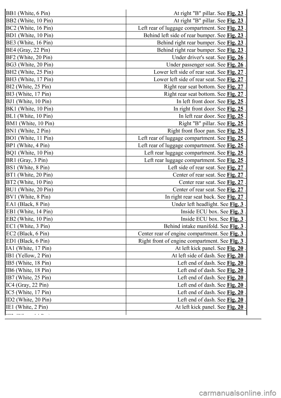
BB1 (White, 6 Pin)At right "B" pillar. See Fig. 23 .
BB2 (White, 10 Pin)At right "B" pillar. See Fig. 23 .
BC2 (White, 16 Pin)Left rear of luggage compartment. See Fig. 23 .
BD1 (White, 10 Pin)Behind left side of rear bumper. See Fig. 23 .
BE3 (White, 16 Pin)Behind right rear bumper. See Fig. 23 .
BE4 (Gray, 22 Pin)Behind right rear bumper. See Fig. 23 .
BF2 (White, 20 Pin)Under driver's seat. See Fig. 26 .
BG3 (White, 20 Pin)Under passenger seat. See Fig. 26 .
BH2 (White, 25 Pin)Lower left side of rear seat. See Fig. 27 .
BH3 (White, 17 Pin)Lower left side of rear seat. See Fig. 27 .
BI2 (White, 25 Pin)Right rear seat bottom. See Fig. 27 .
BI3 (White, 17 Pin)Right rear seat bottom. See Fig. 27 .
BJ1 (White, 10 Pin)In left front door. See Fig. 25 .
BK1 (White, 10 Pin)In right front door. See Fig. 25 .
BL1 (White, 10 Pin)In left rear door. See Fig. 25 .
BM1 (White, 10 Pin)Right "B" pillar. See Fig. 25 .
BN1 (White, 2 Pin)Right front floor pan. See Fig. 25 .
BO1 (White, 11 Pin)Left rear of luggage compartment. See Fig. 25 .
BP1 (White, 4 Pin)Left rear of luggage compartment. See Fig. 25 .
BQ1 (White, 10 Pin)Left rear luggage compartment. See Fig. 25 .
BR1 (Gray, 3 Pin)Left rear luggage compartment. See Fig. 25 .
BS1 (White, 8 Pin)Left side of rear seat. See Fig. 27 .
BT1 (White, 20 Pin)Center of rear seat. See Fig. 27 .
BT2 (White, 10 Pin)Center rear seat. See Fig. 27 .
BU1 (White, 20 Pin)Center of rear seat. See Fig. 27 .
BV1 (White, 8 Pin)In right rear seat back. See Fig. 27 .
EA1 (Black, 8 Pin)Under left headlight. See Fig. 3 .
EB1 (White, 14 Pin)Inside ECU box. See Fig. 3 .
EB2 (White, 10 Pin)Inside ECU box. See Fig. 3 .
EC1 (White, 3 Pin)Behind intake manifold. See Fig. 3 .
EC2 (Black, 6 Pin)Center rear of engine compartment. See Fig. 3 .
ED1 (Black, 6 Pin)Right front of engine compartment. See Fig. 3 .
IA1 (White, 17 Pin)At left kick panel. See Fig. 20 .
IB1 (Yellow, 2 Pin)At left side of dash. See Fig. 20 .
IB5 (White, 18 Pin)Left end of dash. See Fig. 20 .
IB6 (White, 18 Pin)Left end of dash. See Fig. 20 .
IB7 (White, 25 Pin)Left end of dash. See Fig. 20 .
IC4 (Gray, 22 Pin)Left end of dash. See Fig. 20 .
IC5 (White, 17 Pin)Left end of dash. See Fig. 20 .
ID2 (White, 20 Pin)Left end of dash. See Fig. 20 .
IE1 (White, 2 Pin)At left kick panel. See Fig. 20 .
IF3(Wht 14P )
Page 2669 of 4500
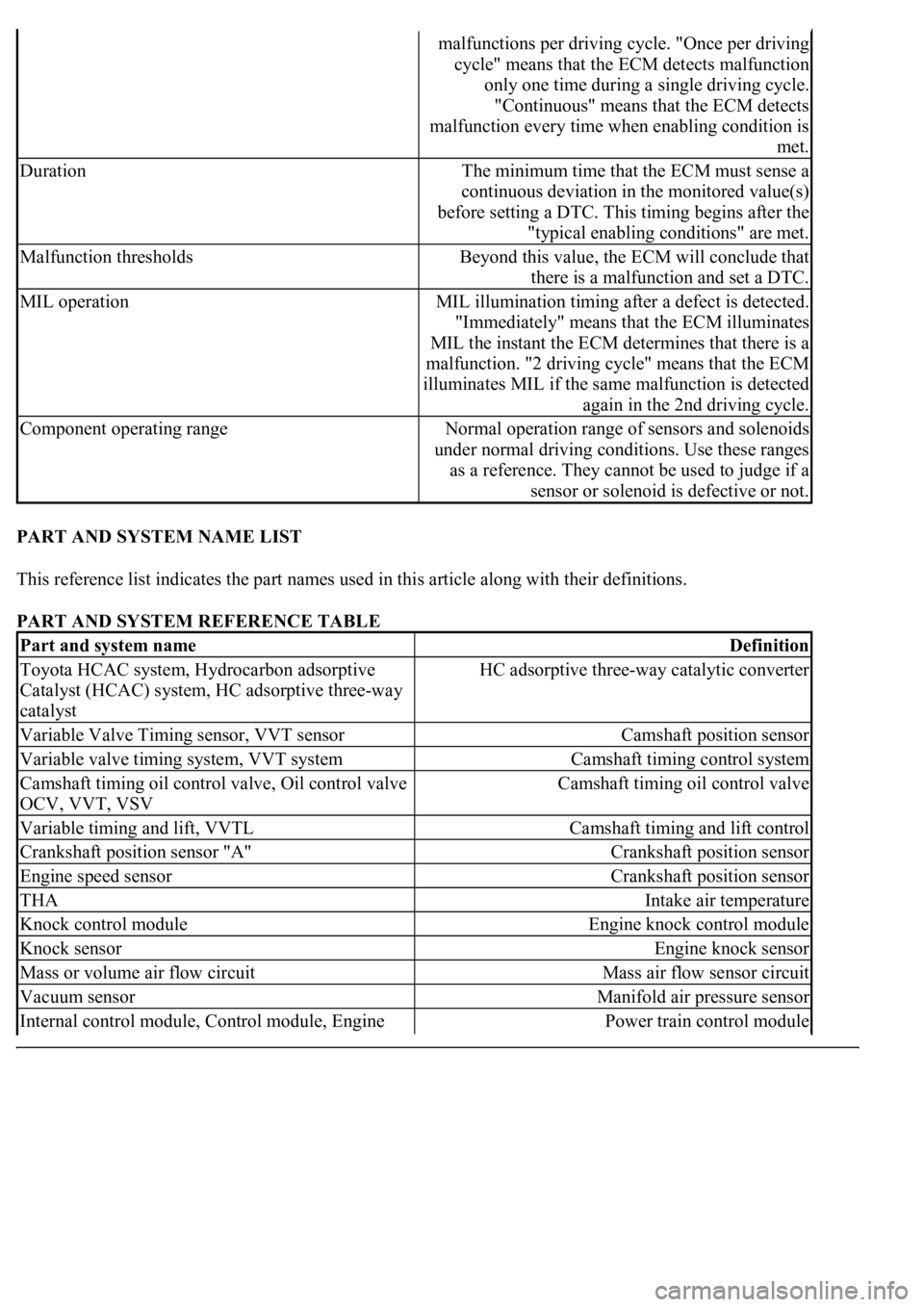
PART AND SYSTEM NAME LIST
This reference list indicates the part names used in this article along with their definitions.
PART AND SYSTEM REFERENCE TABLE
malfunctions per driving cycle. "Once per driving
cycle" means that the ECM detects malfunction
only one time during a single driving cycle.
"Continuous" means that the ECM detects
malfunction every time when enabling condition is
met.
DurationThe minimum time that the ECM must sense a
continuous deviation in the monitored value(s)
before setting a DTC. This timing begins after the
"typical enabling conditions" are met.
Malfunction thresholdsBeyond this value, the ECM will conclude that
there is a malfunction and set a DTC.
MIL operationMIL illumination timing after a defect is detected.
"Immediately" means that the ECM illuminates
MIL the instant the ECM determines that there is a
malfunction. "2 driving cycle" means that the ECM
illuminates MIL if the same malfunction is detected
again in the 2nd driving cycle.
Component operating rangeNormal operation range of sensors and solenoids
under normal driving conditions. Use these ranges
as a reference. They cannot be used to judge if a
sensor or solenoid is defective or not.
Part and system nameDefinition
Toyota HCAC system, Hydrocarbon adsorptive
Catalyst (HCAC) system, HC adsorptive three-way
catalystHC adsorptive three-way catalytic converter
Variable Valve Timing sensor, VVT sensorCamshaft position sensor
Variable valve timing system, VVT systemCamshaft timing control system
Camshaft timing oil control valve, Oil control valve
OCV, VVT, VSVCamshaft timing oil control valve
Variable timing and lift, VVTLCamshaft timing and lift control
Crankshaft position sensor "A"Crankshaft position sensor
Engine speed sensorCrankshaft position sensor
THAIntake air temperature
Knock control moduleEngine knock control module
Knock sensorEngine knock sensor
Mass or volume air flow circuitMass air flow sensor circuit
Vacuum sensorManifold air pressure sensor
Internal control module, Control module, Engine Power train control module
Page 2670 of 4500
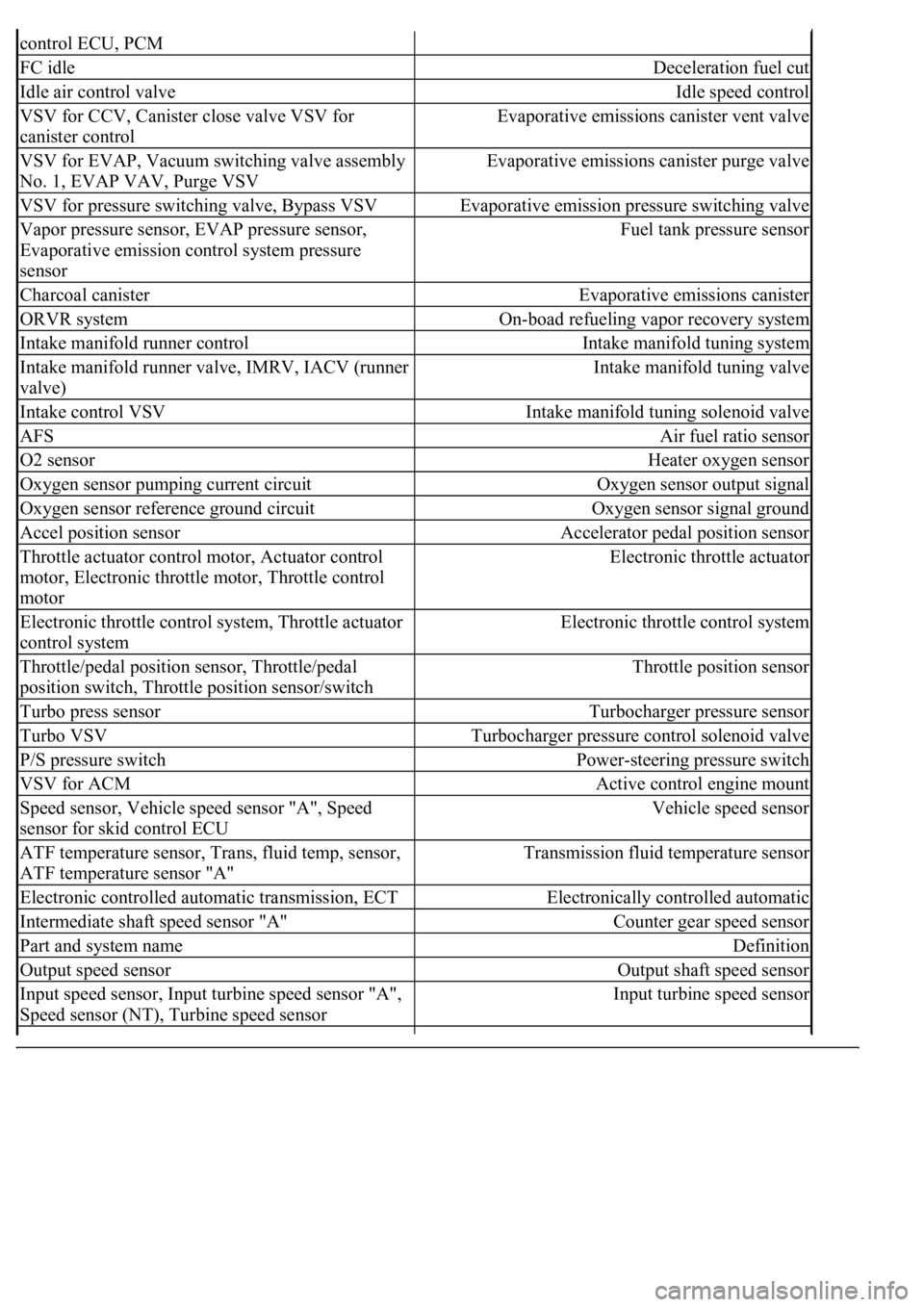
control ECU, PCM
FC idleDeceleration fuel cut
Idle air control valveIdle speed control
VSV for CCV, Canister close valve VSV for
canister controlEvaporative emissions canister vent valve
VSV for EVAP, Vacuum switching valve assembly
No. 1, EVAP VAV, Purge VSVEvaporative emissions canister purge valve
VSV for pressure switching valve, Bypass VSVEvaporative emission pressure switching valve
Vapor pressure sensor, EVAP pressure sensor,
Evaporative emission control system pressure
sensorFuel tank pressure sensor
Charcoal canisterEvaporative emissions canister
ORVR systemOn-boad refueling vapor recovery system
Intake manifold runner controlIntake manifold tuning system
Intake manifold runner valve, IMRV, IACV (runner
valve)Intake manifold tuning valve
Intake control VSVIntake manifold tuning solenoid valve
AFSAir fuel ratio sensor
O2 sensorHeater oxygen sensor
Oxygen sensor pumping current circuitOxygen sensor output signal
Oxygen sensor reference ground circuitOxygen sensor signal ground
Accel position sensorAccelerator pedal position sensor
Throttle actuator control motor, Actuator control
motor, Electronic throttle motor, Throttle control
motorElectronic throttle actuator
Electronic throttle control system, Throttle actuator
control systemElectronic throttle control system
Throttle/pedal position sensor, Throttle/pedal
position switch, Throttle position sensor/switchThrottle position sensor
Turbo press sensorTurbocharger pressure sensor
Turbo VSVTurbocharger pressure control solenoid valve
P/S pressure switchPower-steering pressure switch
VSV for ACMActive control engine mount
Speed sensor, Vehicle speed sensor "A", Speed
sensor for skid control ECUVehicle speed sensor
ATF temperature sensor, Trans, fluid temp, sensor,
ATF temperature sensor "A"Transmission fluid temperature sensor
Electronic controlled automatic transmission, ECTElectronically controlled automatic
Intermediate shaft speed sensor "A"Counter gear speed sensor
Part and system nameDefinition
Output speed sensorOutput shaft speed sensor
<002c00510053005800570003005600530048004800470003005600480051005600520055000f0003002c005100530058005700030057005800550045004c005100480003005600530048004800470003005600480051005600520055000300050024000500
0f0003[
Speed sensor (NT), Turbine speed sensorInput turbine speed sensor
Page 2926 of 4500
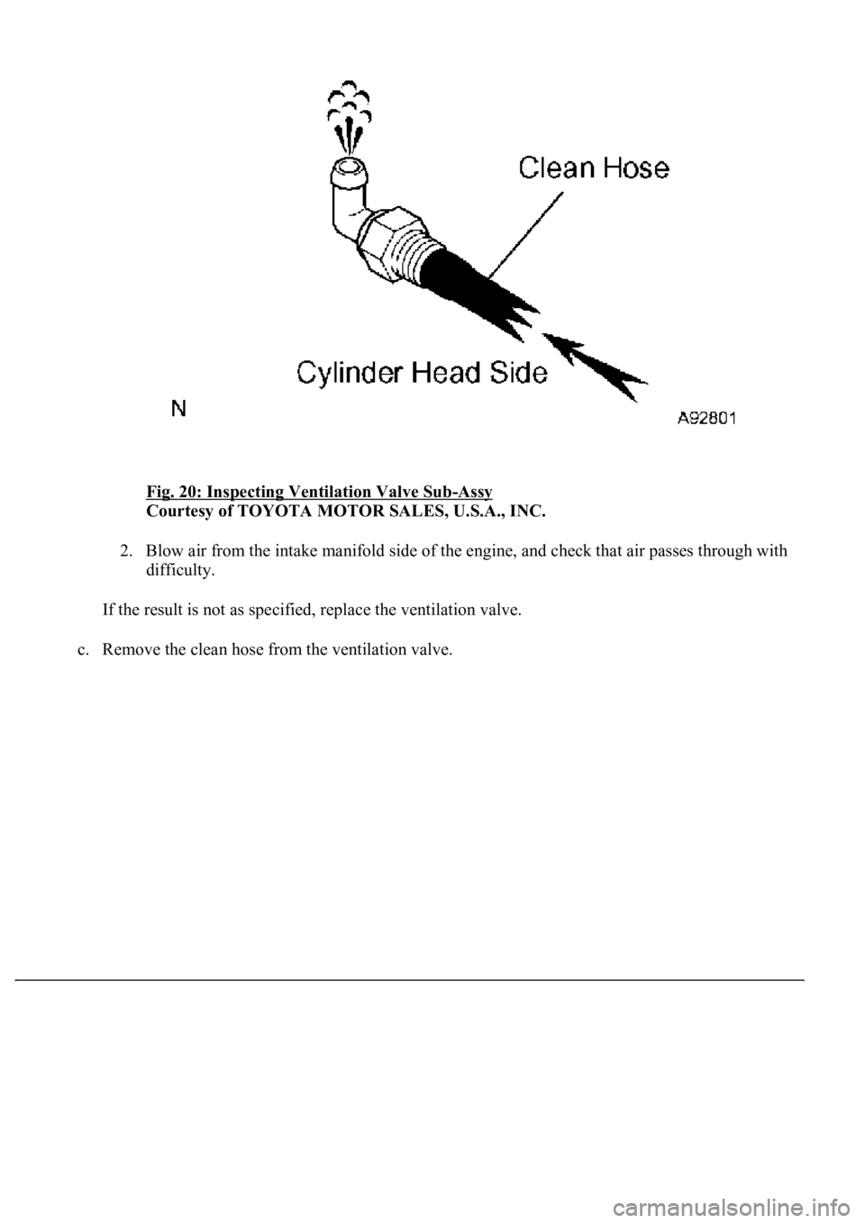
Fig. 20: Inspecting Ventilation Valve Sub-Assy
Courtesy of TOYOTA MOTOR SALES, U.S.A., INC.
2. Blow air from the intake manifold side of the engine, and check that air passes through with
difficulty.
If the result is not as specified, replace the ventilation valve.
c. Remove the clean hose from the ventilation valve.
Page 2927 of 4500
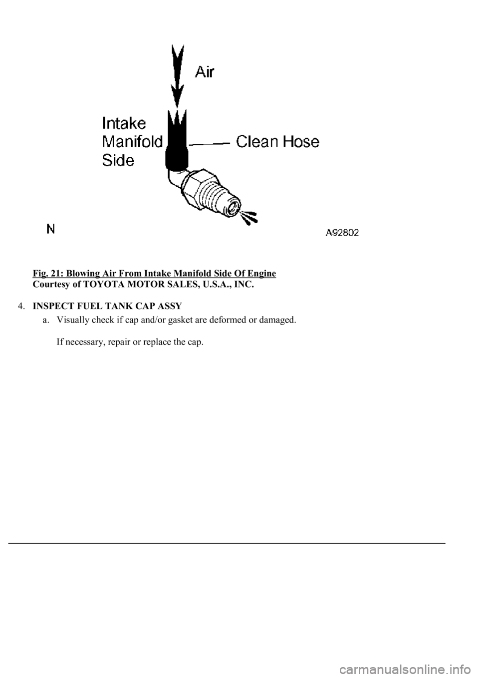
Fig. 21: Blowing Air From Intake Manifold Side Of Engine
Courtesy of TOYOTA MOTOR SALES, U.S.A., INC.
4.INSPECT FUEL TANK CAP ASSY
a. Visually check if cap and/or gasket are deformed or damaged.
If necessar
y, repair or replace the cap.
Page 2961 of 4500
REPLACEMENT
1.DRAIN ENGINE COOLANT (See ENGINE COOLANT
)
2.WORK FOR PREVENTING GASOLINE FROM SPILLING OUT (See PRECAUTION
)
3.DISCONNECT BATTERY NEGATIVE TERMINAL
4.REMOVE V-BANK COVER
5.REMOVE INTAKE AIR CONNECTOR PIPE
6.REMOVE THROTTLE BODY ASSY (See REPLACEMENT
)
7.REMOVE INTAKE MANIFOLD ASSY
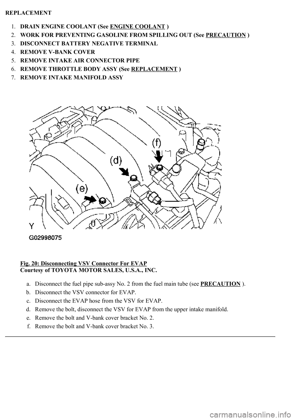
Fig. 20: Disconnecting VSV Connector For EVAP
Courtesy of TOYOTA MOTOR SALES, U.S.A., INC.
a. Disconnect the fuel pipe sub-assy No. 2 from the fuel main tube (see PRECAUTION
).
b. Disconnect the VSV connector for EVAP.
c. Disconnect the EVAP hose from the VSV for EVAP.
d. Remove the bolt, disconnect the VSV for EVAP from the upper intake manifold.
e. Remove the bolt and V-bank cover bracket No. 2.
f. Remove the bolt and V-
bank cover bracket No. 3.