Page 1782 of 4500

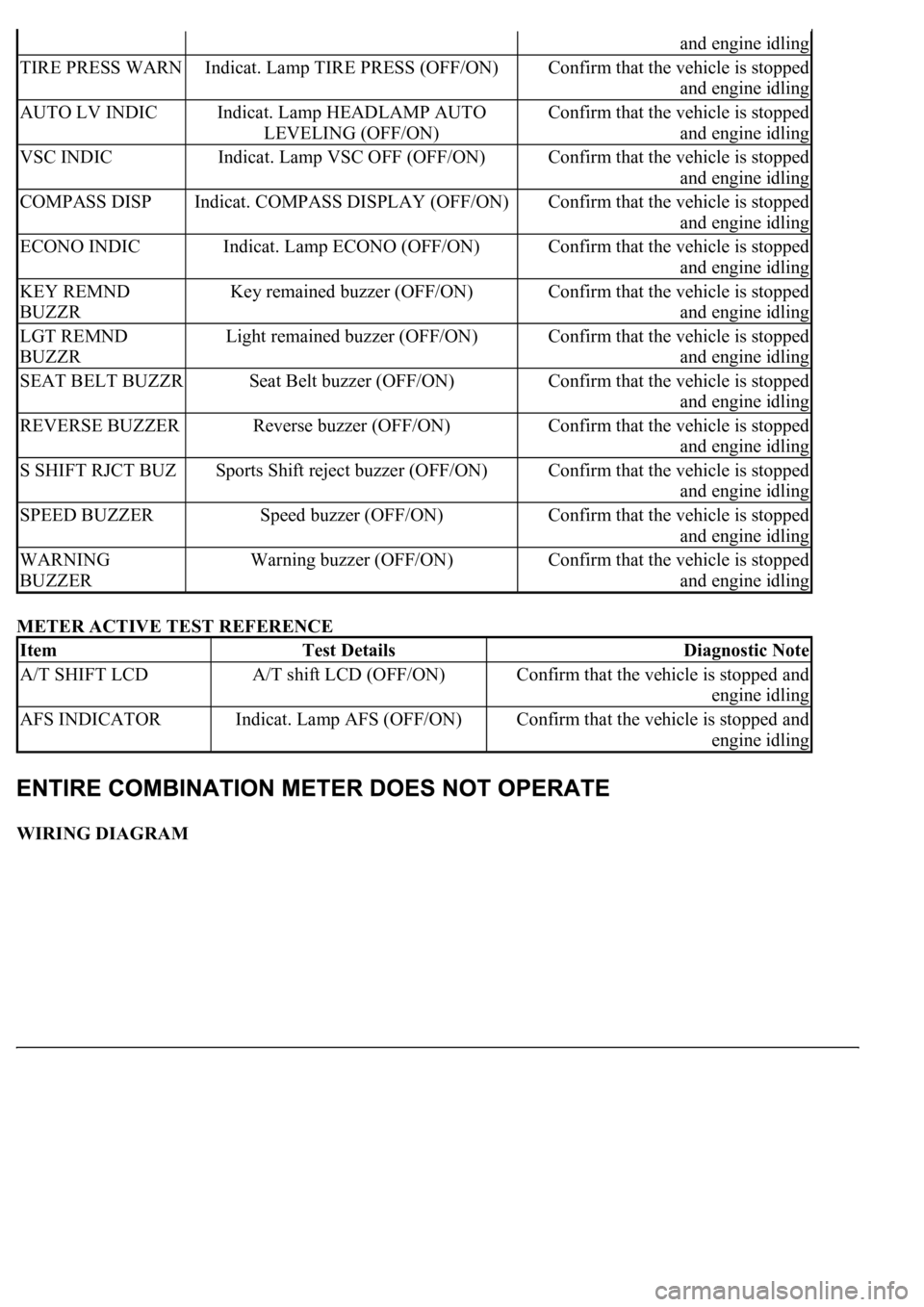
METER ACTIVE TEST REFERENCE
WIRING DIAGRAM
and engine idling
TIRE PRESS WARNIndicat. Lamp TIRE PRESS (OFF/ON)Confirm that the vehicle is stopped
and engine idling
AUTO LV INDICIndicat. Lamp HEADLAMP AUTO
LEVELING (OFF/ON)Confirm that the vehicle is stopped
and engine idling
VSC INDICIndicat. Lamp VSC OFF (OFF/ON)Confirm that the vehicle is stopped
and engine idling
COMPASS DISPIndicat. COMPASS DISPLAY (OFF/ON)Confirm that the vehicle is stopped
and engine idling
ECONO INDICIndicat. Lamp ECONO (OFF/ON)Confirm that the vehicle is stopped
and engine idling
KEY REMND
BUZZRKey remained buzzer (OFF/ON)Confirm that the vehicle is stopped
and engine idling
LGT REMND
BUZZRLight remained buzzer (OFF/ON)Confirm that the vehicle is stopped
and engine idling
SEAT BELT BUZZRSeat Belt buzzer (OFF/ON)Confirm that the vehicle is stopped
and engine idling
REVERSE BUZZERReverse buzzer (OFF/ON)Confirm that the vehicle is stopped
and engine idling
S SHIFT RJCT BUZSports Shift reject buzzer (OFF/ON)Confirm that the vehicle is stopped
and engine idling
SPEED BUZZERSpeed buzzer (OFF/ON)Confirm that the vehicle is stopped
and engine idling
WARNING
BUZZERWarning buzzer (OFF/ON)Confirm that the vehicle is stopped
and engine idling
ItemTest DetailsDiagnostic Note
A/T SHIFT LCDA/T shift LCD (OFF/ON)Confirm that the vehicle is stopped and
engine idling
AFS INDICATORIndicat. Lamp AFS (OFF/ON)Confirm that the vehicle is stopped and
engine idling
Page 1963 of 4500
15. Return the reflector to the original position and read the current angle.
DIVERGENCE OF BEAM AXIS TABLE
HINT:
When the values displayed on the screen are normal, the values are within the above range. If the
value is out of range, check the installation condition of the bumper reinforcement, etc.
16. Turn the headlamp dimmer switch to the TAIL position.
17. Press the "ENTER" key.
Fig. 16: Identifying "ENTER" Key
UPPER/LOWER SIDE-2° TO +2°
RIGHT/LEFT SIDE-4° TO +4°
Page 3788 of 4500
Fig. 5: Removing Front Bumper Cover
Courtesy of TOYOTA MOTOR SALES, U.S.A., INC.
6.REMOVE HEADLAMP CLEANER (FROM MOTOR TO JOINT) HOSE (W/ HEADLAMP
CLEANER)
a. Disconnect the cleaner hose joint from the actuator.
HINT:
Be careful when removing the cleaner hose from the actuator, because washer fluid will spill.
b. Disconnect the cleaner hose from the bumper cover.
7.REMOVE FRONT BUMPER ENERGY ABSORBER
8.REMOVE RADIATOR SUPPORT REINFORCEMENT LOWER
a. Remove the 2 bolts.
b. Unlock the 2 claws and partially remove the reinforcement lower by angling it towards yourself.
HINT:
It is not necessar
y to fully remove the reinforcement lower completely. Partially remove it so that the
Page 3790 of 4500
Fig. 7: Removing Fog Lamp Assy LH
Courtesy of TOYOTA MOTOR SALES, U.S.A., INC.
12.REMOVE FOG LAMP ASSY RH
HINT:
Use the same procedures described for the LH side.
13.REMOVE HEADLAMP CLEANER WASHER NOZZLE (W/ HEADLAMP CLEANER)
a. Using a screwdriver, pull out the 2 washer nozzles.
HINT:
Tape the screwdriver tip before use.
Page 3791 of 4500
Fig. 8: Removing Headlamp Cleaner Washer Nozzle (W/Headlamp Cleaner)
Courtesy of TOYOTA MOTOR SALES, U.S.A., INC.
14.REMOVE HEADLAMP WASHER ACTUATOR SUB-ASSY LH (W/ HEADLAMP CLEANER)
a. Remove the screw and actuator.
15.REMOVE HEADLAMP WASHER ACTUATOR SUB-ASSY RH (W/ HEADLAMP CLEANER)
a. Remove the screw and actuator.
16.REMOVE ULTRASONIC SENSOR NO. 1 (w/ CLEARANCE SONAR SYSTEM)
a. Using a screwdriver, remove the retainer and sensor.
HINT:
Tape the screwdriver tip before use.
17.REMOVE FRONT BUMPER EXTENSION MOUNTING BRACKET
a. Remove the 2 screws and mounting bracket.
18.REMOVE FRONT BUMPER SIDE RETAINER LH
a. Use a drill that has a tip of less than phis 4 mm (0.16 in.).
b. Tape the drill tip as shown in Fig. 9.