Page 704 of 4500
Fig. 2: Audio System Diagram
Courtesy of TOYOTA MOTOR SALES, U.S.A., INC.
Input and output signals of each ECU.
TRANSMITTING ECU (TRANSMITTER) CHART
1.CD (Compact Disc) player outline
a. A compact disc player uses a laser pickup to read digital signals recorded on a compact disc (CD).
Transmitting ECU
(Transmitter)
Receiving ECUSignalsCommunication method
Driver Side J/B ECUSteering Pad SwitchACC SW SignalBEAN (Column Bus)
Driver Side J/B ECUSteering Pad SwitchTaillight ON SignalBEAN (Column Bus)
Steering Pad SwitchRadio Receiver AssyAudio SignalBEAN (Column Bus) AVC-
LAN
Page 705 of 4500

By converting the digital signals to analog, it can play music and other things. In general, CD
players can play 4.7-inch (12 cm) or 3.2-inch (8 cm) disc.
HINT:
Do not disassemble any part of the CD player.
Do not apply oil to the CD player.
Do not insert anything but a CD into the CD player.
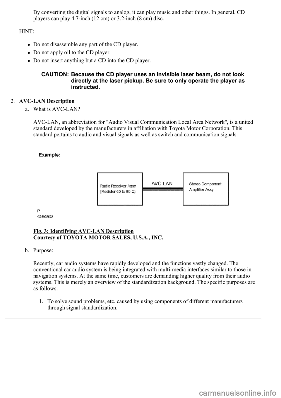
2.AVC-LAN Description
a. What is AVC-LAN?
AVC-LAN, an abbreviation for "Audio Visual Communication Local Area Network", is a united
standard developed by the manufacturers in affiliation with Toyota Motor Corporation. This
standard pertains to audio and visual signals as well as switch and communication signals.
Fig. 3: Identifying AVC
-LAN Description
Courtesy of TOYOTA MOTOR SALES, U.S.A., INC.
b. Purpose:
Recently, car audio systems have rapidly developed and the functions vastly changed. The
conventional car audio system is being integrated with multi-media interfaces similar to those in
navigation systems. At the same time, customers are demanding higher quality from their audio
systems. This is merely an overview of the standardization background. The specific purposes are
as follows.
1. To solve sound problems, etc. caused by using components of different manufacturers
through signal standardization.
Page 753 of 4500
OK: Radio receiver assy is properly installed.
NG: REINSTALL THE RADIO RECEIVER ASSY PROPERLY
OK: PROCEED TO NEXT CIRCUIT INSPECTION SHOWN IN PROBLEM SYMPTOMS
TABLE
INSPECTION PROCEDURE
1.CHECK AUDIO SETTINGS
a. Set "BASS", "MID" and "TREB" to the initial value and check if sound is normal.
OK: Return to normal.
OK: END
NG: PROCEED TO NEXT CIRCUIT INSPECTION SHOWN IN PROBLEM SYMPTOMS
TABLE
INSPECTION PROCEDURE
1.CHECK FOR ANY FOREIGN OBJECT
a. Check for any foreign objects.
1. Check that no foreign objects or defects are detected in the cassette tape player of the radio
receiver assembly.
OK: No foreign objects or defects are detected.
NG: REMOVE FOREIGN OBJECT
OK: Go to next step
2.CHECK CASSETTE TAPE
a. Check the cassette tape.
1. Check that the cassette tape is a normal tape to which music or voice is recorded.
OK: Proper cassette tape to which music or voice is recorded.
NG: CASSETTE TAPE FAULTY
OK: Go to next step
Page 755 of 4500
INSPECTION PROCEDURE
1.REPLACE CASSETTE TAPE WITH ANOTHER AND RECHECK
a. Replace the cassette tape with another one and recheck.
1. Replace the cassette tape with another normal one to see if the same trouble occurs again.
OK: Malfunction disappears.
OK: CASSETTE TAPE FAULTY
NG: Go to next step
2.CHECK FOR ANY FOREIGN OBJECT
a. Check for foreign objects.
1. Check that no foreign objects or defects are detected in the cassette tape player.
OK: No foreign objects or defects are detected.
NG: REMOVE FOREIGN OBJECT
OK: Go to next step
3.CLEAN HEAD AND CHECK OPERATION
a. Head cleaning
1. Raise the cassette door with your finger. Using a pencil or similar object, push in the guide.
2. Using a cleaning pen or cotton applicator soaked in cleaner, clean the head surface, pinch
rollers and capstans.
3. Check if the same trouble occurs again.
OK: Malfunction disappears.
NG: REPLACE RADIO RECEIVER ASSY (SEE REPLACEMENT
)
OK: HEAD DIRTY
Page 756 of 4500
Fig. 41: Raising Cassette Door
Courtesy of TOYOTA MOTOR SALES, U.S.A., INC.
INSPECTION PROCEDURE
1.CHECK FOR ANY FOREIGN OBJECT
a. Check for foreign objects.
1. Check that no foreign objects or defects are detected in the cassette tape player of the radio
receiver assy.
OK: No foreign objects or defects are detected.
NG: REMOVE FOREIGN OBJECT
OK: Go to next step
2.REPLACE CASSETTE TAPE WITH ANOTHER AND RECHECK (BELOW 90 MIN.)
a. Replace the cassette tape with another one and recheck.
1. Replace the cassette tape with another normal one (90 minutes or less) to see if the same
Page 4447 of 4500

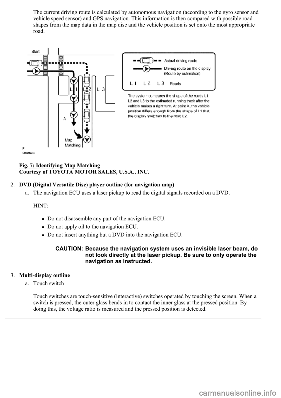
The current driving route is calculated by autonomous navigation (according to the gyro sensor and
vehicle speed sensor) and GPS navigation. This information is then compared with possible road
shapes from the map data in the map disc and the vehicle position is set onto the most appropriate
road.
Fig. 7: Identifying Map Matching
Courtesy of TOYOTA MOTOR SALES, U.S.A., INC.
2.DVD (Digital Versatile Disc) player outline (for navigation map)
a. The navigation ECU uses a laser pickup to read the digital signals recorded on a DVD.
HINT:
Do not disassemble any part of the navigation ECU.
Do not apply oil to the navigation ECU.
Do not insert anything but a DVD into the navigation ECU.
3.Multi-display outline
a. Touch switch
Touch switches are touch-sensitive (interactive) switches operated by touching the screen. When a
switch is pressed, the outer glass bends in to contact the inner glass at the pressed position. By
doing this, the voltage ratio is measured and the pressed position is detected.