Page 1028 of 4500
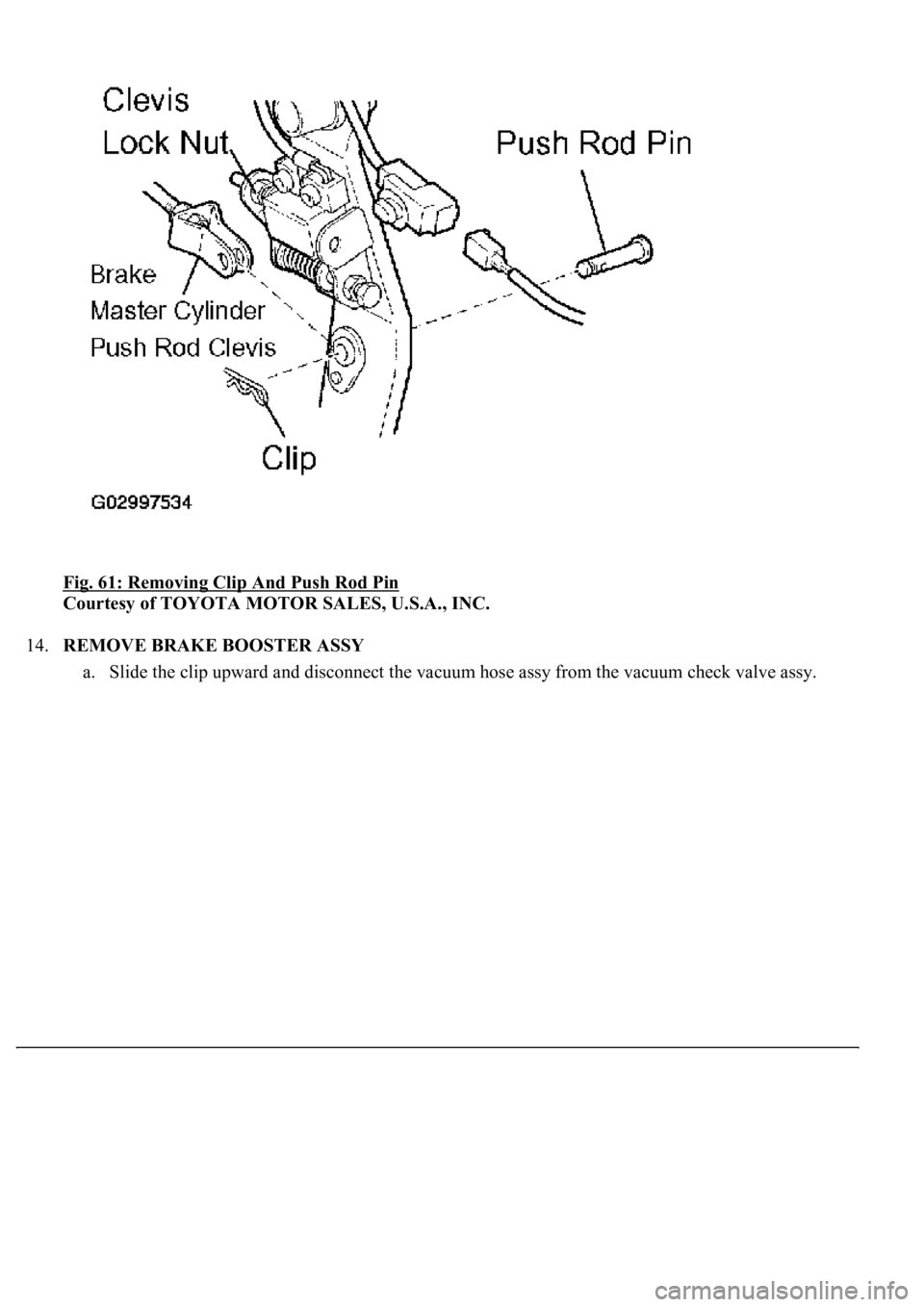
Fig. 61: Removing Clip And Push Rod Pin
Courtesy of TOYOTA MOTOR SALES, U.S.A., INC.
14.REMOVE BRAKE BOOSTER ASSY
a. Slide the clip upward and disconnect the vacuum hose ass
y from the vacuum check valve assy.
Page 1029 of 4500
Fig. 62: Disconnecting Vacuum Hose Assy From Vacuum Check Valve Assy
Courtesy of TOYOTA MOTOR SALES, U.S.A., INC.
b. Remove the 4 nuts and pull out the brake booster assy.
c. Remove the brake booster
gasket.
Page 1032 of 4500
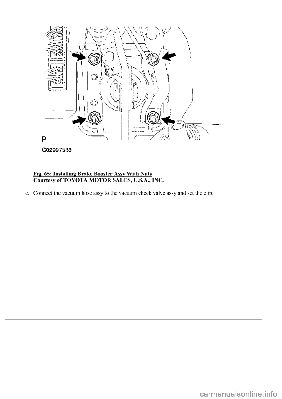
Fig. 65: Installing Brake Booster Assy With Nuts
Courtesy of TOYOTA MOTOR SALES, U.S.A., INC.
c. Connect the vacuum hose assy to the vacuum check valve assy and set the clip.
Page 4409 of 4500
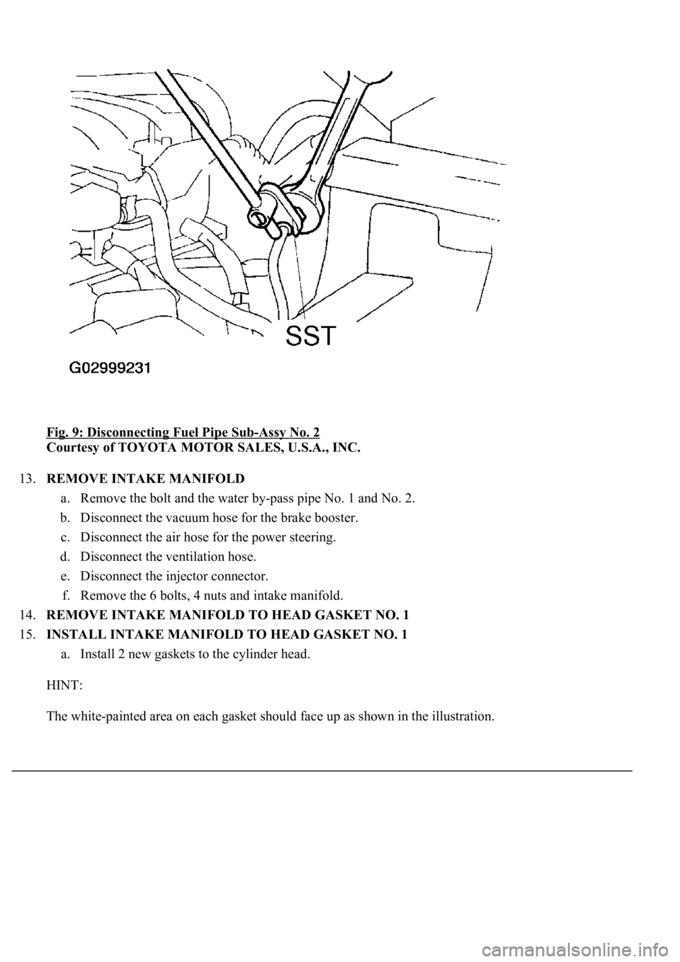
Fig. 9: Disconnecting Fuel Pipe Sub-Assy No. 2
Courtesy of TOYOTA MOTOR SALES, U.S.A., INC.
13.REMOVE INTAKE MANIFOLD
a. Remove the bolt and the water by-pass pipe No. 1 and No. 2.
b. Disconnect the vacuum hose for the brake booster.
c. Disconnect the air hose for the power steering.
d. Disconnect the ventilation hose.
e. Disconnect the injector connector.
f. Remove the 6 bolts, 4 nuts and intake manifold.
14.REMOVE INTAKE MANIFOLD TO HEAD GASKET NO. 1
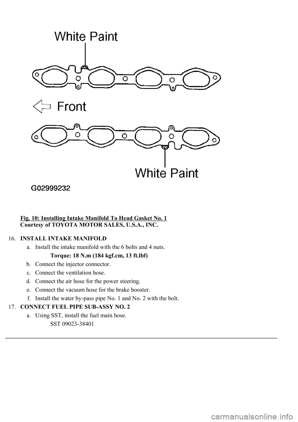
15.INSTALL INTAKE MANIFOLD TO HEAD GASKET NO. 1
a. Install 2 new gaskets to the cylinder head.
HINT:
The white-painted area on each gasket should face up as shown in the illustration.
Page 4410 of 4500
Fig. 10: Installing Intake Manifold To Head Gasket No. 1
Courtesy of TOYOTA MOTOR SALES, U.S.A., INC.
16.INSTALL INTAKE MANIFOLD
a. Install the intake manifold with the 6 bolts and 4 nuts.
Torque: 18 N.m (184 kgf.cm, 13 ft.lbf)
b. Connect the injector connector.
c. Connect the ventilation hose.
d. Connect the air hose for the power steering.
e. Connect the vacuum hose for the brake booster.
f. Install the water by-pass pipe No. 1 and No. 2 with the bolt.
17.CONNECT FUEL PIPE SUB-ASSY NO. 2
a. Using SST, install the fuel main hose.
SST 09023-38401