Page 1588 of 4500
Fig. 1: Locating Climate Control Seat System Components (1 Of 2)
Courtesy of TOYOTA MOTOR SALES, U.S.A., INC.
Page 1589 of 4500
Fig. 2: Locating Climate Control Seat System Components (2 Of 2)
Courtesy of TOYOTA MOTOR SALES, U.S.A., INC.
Page 1590 of 4500
Fig. 3: Climate Control Seat System Diagram
Courtesy of TOYOTA MOTOR SALES, U.S.A., INC.
Page 1591 of 4500
COMMUNICATION
1.GENERAL
The climate control seat system creates cold or warm air to increase the comfort of seats that have
become hot or cold.
The air is heated or cooled by the Peltier element on the back of the seat cushion pad and seatback. The
air is then sent to the seat cushion and seatback with the fan installed under the seat. The fan is operated
by pressing the climate control seat switch.
The climate control seat switch has several modes that vary the quantity of air to be sent to the seat. There
are 7 modes in total: 3 cooled air modes, 3 heated air modes and ventilation mode.
HINT:
When the highest level for cooled air operates for 15 minutes, the quantity of air falls 1 level.
2.FUNCTION OF MAIN COMPONENT
Fig. 4: Main Component Function Table
Courtesy of TOYOTA MOTOR SALES, U.S.A., INC.
3.SYSTEM OPERATION
SenderReceiverSignalLine
Climate control ECUECMIdle-up signalBEAN (Door bus), CAN
Page 1592 of 4500
Fig. 5: System Operation Chart (1 Of 2)
Courtesy of TOYOTA MOTOR SALES, U.S.A., INC.
Fig. 6: System Operation Chart (2 Of 2)
Courtesy of TOYOTA MOTOR SALES, U.S.A., INC.
HINT
Use this procedure to troubleshoot the climate control seat system.
The hand-held tester should be used in step 3.
1.VEHICLE BROUGHT TO WORKSHOP
2.CUSTOMER PROBLEM ANALYSIS CHECK AND SYMPTOM CHECK (See CUSTOMER
Page 1594 of 4500
Fig. 7: Customer Problem Analysis Check Sheet
Courtesy of TOYOTA MOTOR SALES, U.S.A., INC.
1.CHECK SEAT CLIMATE CONTROL BLOWER LH (FR) (CLIMATE CONTROL ECU)
Page 1595 of 4500
Fig. 8: Identifying Terminals Of Climate Control ECU - LH (FR)
Courtesy of TOYOTA MOTOR SALES, U.S.A., INC.
a. Disconnect the C20 and S48 blower connectors.
b. Measure the voltage and resistance of the wire harness side connectors.
Standard:
TERMINAL DESCRIPTION AND SPECIFIED CONDITION
Symbols
(Terminal
No.)Wiring
ColorTerminal
DescriptionConditionSpecified
Condition
E (C20 - 8) -
Body groundW-B -
Body
ground
GroundAlwaysBelow 1 ohms
IG (C20 -7) -
Body groundB - Body
groundPower sourceIgnition switch ON10 to 14 V
V5 (C20 - 13)
- VG (C20 - 9)GR-R - LPower supply for
volume switchAlways5 kohms
VS (C20 - 12)
- VG (20 - 9)R-B - LVolume switch signalTurn volume switch: Max0 ohms --> 5
kohms
TB5 (C20 - 4)
- TBS (20 - 3)L-Y -
BR-WSeatback temperature
sensorSeatback temperature: 10°C --
> 30°C (50°F --> 86°F)Approx. 3.7
kohms -->
Approx. 1.7
Page 1596 of 4500

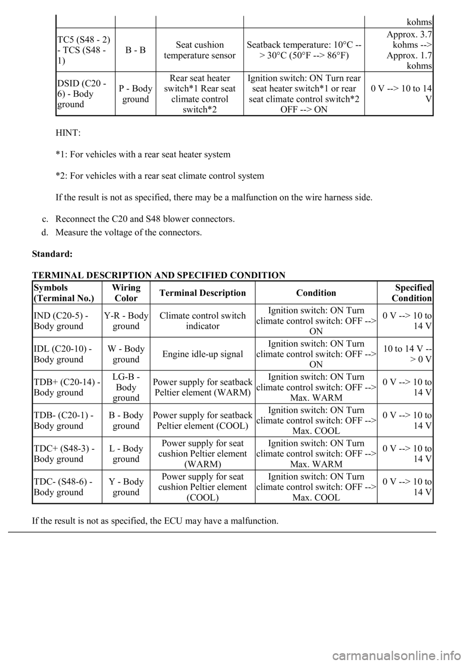
HINT:
*1: For vehicles with a rear seat heater system
*2: For vehicles with a rear seat climate control system
If the result is not as specified, there may be a malfunction on the wire harness side.
c. Reconnect the C20 and S48 blower connectors.
d. Measure the voltage of the connectors.
Standard:
TERMINAL DESCRIPTION AND SPECIFIED CONDITION
If the result is not as specified, the ECU ma
y have a malfunction.
kohms
TC5 (S48 - 2)
- TCS (S48 -
1)
B - BSeat cushion
temperature sensorSeatback temperature: 10°C --
> 30°C (50°F --> 86°F)
Approx. 3.7
kohms -->
Approx. 1.7
kohms
DSID (C20 -
6) - Body
groundP - Body
ground
Rear seat heater
switch*1 Rear seat
climate control
switch*2Ignition switch: ON Turn rear
seat heater switch*1 or rear
seat climate control switch*2
OFF --> ON
0 V --> 10 to 14
V
Symbols
(Terminal No.)Wiring
ColorTerminal DescriptionConditionSpecified
Condition
IND (C20-5) -
Body groundY-R - Body
groundClimate control switch
indicatorIgnition switch: ON Turn
climate control switch: OFF -->
ON0 V --> 10 to
14 V
IDL (C20-10) -
Body groundW - Body
groundEngine idle-up signal
Ignition switch: ON Turn
climate control switch: OFF -->
ON10 to 14 V --
> 0 V
TDB+ (C20-14) -
Body groundLG-B -
Body
groundPower supply for seatback
Peltier element (WARM)Ignition switch: ON Turn
climate control switch: OFF -->
Max. WARM0 V --> 10 to
14 V
TDB- (C20-1) -
Body groundB - Body
groundPower supply for seatback
Peltier element (COOL)Ignition switch: ON Turn
climate control switch: OFF -->
Max. COOL0 V --> 10 to
14 V
TDC+ (S48-3) -
Body groundL - Body
groundPower supply for seat
cushion Peltier element
(WARM)Ignition switch: ON Turn
climate control switch: OFF -->
Max. WARM0 V --> 10 to
14 V
TDC- (S48-6) -
Body groundY - Body
groundPower supply for seat
cushion Peltier element
(COOL)Ignition switch: ON Turn
climate control switch: OFF -->
Max. COOL0 V --> 10 to
14 V