Page 671 of 4500
OVERHAUL - FIXED)
5.REMOVE REAR DOOR SCUFF PLATE RH (See REPLACEMENT
)
6.REMOVE REAR DOOR SCUFF PLATE LH (See REPLACEMENT
)
7.REMOVE REAR DOOR OPENING TRIM WEATHERSTRIP RH (See REPLACEMENT
)
8.REMOVE REAR DOOR OPENING TRIM WEATHERSTRIP LH (See REPLACEMENT
)
9.REMOVE REAR SEAT SIDE COVER RH (See REPLACEMENT
)
10.REMOVE REAR SEAT SIDE COVER LH (See REPLACEMENT
)
11.REMOVE ROOF SIDE GARNISH INNER RH (See REPLACEMENT
)
12.REMOVE ROOF SIDE GARNISH INNER LH (See REPLACEMENT
)
13.REMOVE CENTER STOP LAMP ASSY (See REPLACEMENT
)
14.REMOVE REAR SPEAKER GRILLE SUB-ASSY (See REPLACEMENT
)
15.REMOVE PACKAGE TRAY TRIM PANEL ASSY (See REPLACEMENT
)
16.REMOVE STEREO COMPONENT SPEAKER ASSY REAR
a. Disconnect the connector.
b. Remove the 4 screws and stereo component speaker assy rear.
Fig. 34: Removing Stereo Component Speaker Assy Rear Screws
Courtesy of TOYOTA MOTOR SALES, U.S.A., INC.
Page 685 of 4500
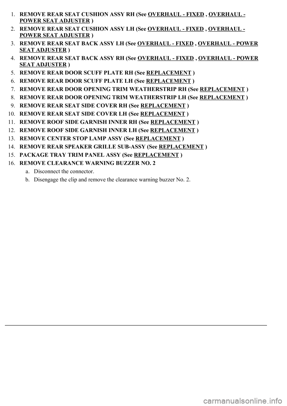
1.REMOVE REAR SEAT CUSHION ASSY RH (See OVERHAUL - FIXED , OVERHAUL -
POWER SEAT ADJUSTER
)
2.REMOVE REAR SEAT CUSHION ASSY LH (See OVERHAUL
- FIXED , OVERHAUL -
POWER SEAT ADJUSTER
)
3.REMOVE REAR SEAT BACK ASSY LH (See OVERHAUL
- FIXED , OVERHAUL - POWER
SEAT ADJUSTER )
4.REMOVE REAR SEAT BACK ASSY RH (See OVERHAUL
- FIXED , OVERHAUL - POWER
SEAT ADJUSTER )
5.REMOVE REAR DOOR SCUFF PLATE RH (See REPLACEMENT
)
6.REMOVE REAR DOOR SCUFF PLATE LH (See REPLACEMENT
)
7.REMOVE REAR DOOR OPENING TRIM WEATHERSTRIP RH (See REPLACEMENT
)
8.REMOVE REAR DOOR OPENING TRIM WEATHERSTRIP LH (See REPLACEMENT
)
9.REMOVE REAR SEAT SIDE COVER RH (See REPLACEMENT
)
10.REMOVE REAR SEAT SIDE COVER LH (See REPLACEMENT
)
11.REMOVE ROOF SIDE GARNISH INNER RH (See REPLACEMENT
)
12.REMOVE ROOF SIDE GARNISH INNER LH (See REPLACEMENT
)
13.REMOVE CENTER STOP LAMP ASSY (See REPLACEMENT
)
14.REMOVE REAR SPEAKER GRILLE SUB-ASSY (See REPLACEMENT
)
15.PACKAGE TRAY TRIM PANEL ASSY (See REPLACEMENT
)
16.REMOVE CLEARANCE WARNING BUZZER NO. 2
a. Disconnect the connector.
b. Disengage the clip and remove the clearance warning buzzer No. 2.
Page 688 of 4500
1.REMOVE TELEPHONE ANTENNA ROD
a. Rotate the telephone antenna rod in the direction indicated by the arrow to remove it.
Fig. 49: Removing Telephone Antenna Rod
Courtesy of TOYOTA MOTOR SALES, U.S.A., INC.
2.REMOVE ROOF HEADLINING ASSY (See step 37 on REPLACEMENT
)
3.REMOVE TELEPHONE ANTENNA BASE
a. Disconnect the connector.
b. Remove the 2 nuts and telephone antenna base.
Page 689 of 4500
Fig. 50: Removing Telephone Antenna Base Nuts
Courtesy of TOYOTA MOTOR SALES, U.S.A., INC.
REPLACEMENT
HINT:
See LOCATION .
Installation is in the reverse order of removal.
1.REMOVE LUGGAGE COMPARTMENT FLOOR MAT (See step 18 on OVERHAUL
)
2.REMOVE DECK TRIM SIDE BOARD RH (See OVERHAUL
)
3.REMOVE REAR FLOOR FINISH PLATE (See step 20 on OVERHAUL
)
4.REMOVE LUGGAGE COMPARTMENT TRIM COVER FRONT (See step 19 on OVERHAUL
)
5.REMOVE LUGGAGE COMPARTMENT TRIM COVER ASSY RH (See step 22 on
OVERHAUL
)
6.REMOVE ROOF HEADLINING ASSY (See step 37 on REPLACEMENT
)
7.REMOVE ANTENNA CORD SUB-ASSY
a. Disconnect the connector.
b. Remove the bolt.
c. Disengage the 5 clips and remove the antenna cord sub-assy.
Page 2422 of 4500
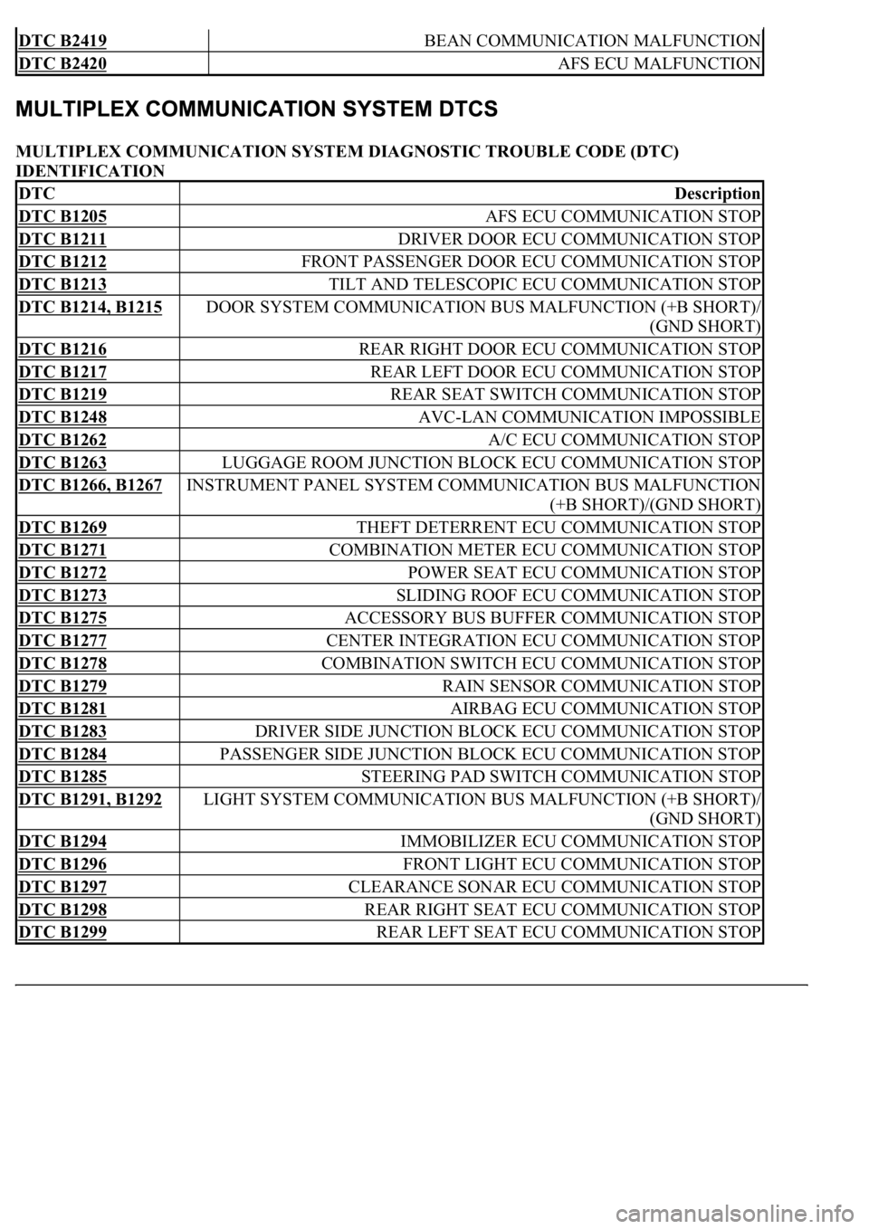
MULTIPLEX COMMUNICATION SYSTEM DIAGNOSTIC TROUBLE CODE (DTC)
IDENTIFICATION
DTC B2419 BEAN COMMUNICATION MALFUNCTION
DTC B2420 AFS ECU MALFUNCTION
DTCDescription
DTC B1205 AFS ECU COMMUNICATION STOP
DTC B1211 DRIVER DOOR ECU COMMUNICATION STOP
DTC B1212 FRONT PASSENGER DOOR ECU COMMUNICATION STOP
DTC B1213 TILT AND TELESCOPIC ECU COMMUNICATION STOP
DTC B1214, B1215 DOOR SYSTEM COMMUNICATION BUS MALFUNCTION (+B SHORT)/
(GND SHORT)
DTC B1216 REAR RIGHT DOOR ECU COMMUNICATION STOP
DTC B1217 REAR LEFT DOOR ECU COMMUNICATION STOP
DTC B1219 REAR SEAT SWITCH COMMUNICATION STOP
DTC B1248 AVC-LAN COMMUNICATION IMPOSSIBLE
DTC B1262 A/C ECU COMMUNICATION STOP
DTC B1263 LUGGAGE ROOM JUNCTION BLOCK ECU COMMUNICATION STOP
DTC B1266, B1267 INSTRUMENT PANEL SYSTEM COMMUNICATION BUS MALFUNCTION
(+B SHORT)/(GND SHORT)
DTC B1269 THEFT DETERRENT ECU COMMUNICATION STOP
DTC B1271 COMBINATION METER ECU COMMUNICATION STOP
DTC B1272 POWER SEAT ECU COMMUNICATION STOP
DTC B1273 SLIDING ROOF ECU COMMUNICATION STOP
DTC B1275 ACCESSORY BUS BUFFER COMMUNICATION STOP
DTC B1277 CENTER INTEGRATION ECU COMMUNICATION STOP
DTC B1278 COMBINATION SWITCH ECU COMMUNICATION STOP
DTC B1279 RAIN SENSOR COMMUNICATION STOP
DTC B1281 AIRBAG ECU COMMUNICATION STOP
DTC B1283 DRIVER SIDE JUNCTION BLOCK ECU COMMUNICATION STOP
DTC B1284 PASSENGER SIDE JUNCTION BLOCK ECU COMMUNICATION STOP
DTC B1285 STEERING PAD SWITCH COMMUNICATION STOP
DTC B1291, B1292 LIGHT SYSTEM COMMUNICATION BUS MALFUNCTION (+B SHORT)/
(GND SHORT)
DTC B1294 IMMOBILIZER ECU COMMUNICATION STOP
DTC B1296 FRONT LIGHT ECU COMMUNICATION STOP
DTC B1297 CLEARANCE SONAR ECU COMMUNICATION STOP
DTC B1298 REAR RIGHT SEAT ECU COMMUNICATION STOP
DTC B1299 REAR LEFT SEAT ECU COMMUNICATION STOP
Page 2628 of 4500
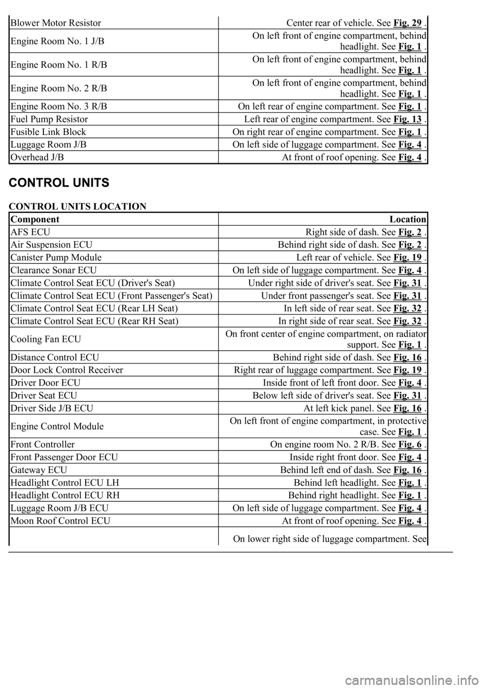
CONTROL UNITS LOCATION
Blower Motor ResistorCenter rear of vehicle. See Fig. 29 .
Engine Room No. 1 J/BOn left front of engine compartment, behind
headlight. See Fig. 1
.
Engine Room No. 1 R/BOn left front of engine compartment, behind
headlight. See Fig. 1
.
Engine Room No. 2 R/BOn left front of engine compartment, behind
headlight. See Fig. 1
.
Engine Room No. 3 R/BOn left rear of engine compartment. See Fig. 1 .
Fuel Pump ResistorLeft rear of engine compartment. See Fig. 13 .
Fusible Link BlockOn right rear of engine compartment. See Fig. 1 .
Luggage Room J/BOn left side of luggage compartment. See Fig. 4 .
Overhead J/BAt front of roof opening. See Fig. 4 .
ComponentLocation
AFS ECURight side of dash. See Fig. 2 .
Air Suspension ECUBehind right side of dash. See Fig. 2 .
Canister Pump ModuleLeft rear of vehicle. See Fig. 19 .
Clearance Sonar ECUOn left side of luggage compartment. See Fig. 4 .
Climate Control Seat ECU (Driver's Seat)Under right side of driver's seat. See Fig. 31 .
Climate Control Seat ECU (Front Passenger's Seat)Under front passenger's seat. See Fig. 31 .
Climate Control Seat ECU (Rear LH Seat)In left side of rear seat. See Fig. 32 .
Climate Control Seat ECU (Rear RH Seat)In right side of rear seat. See Fig. 32 .
Cooling Fan ECUOn front center of engine compartment, on radiator
support. See Fig. 1
.
Distance Control ECUBehind right side of dash. See Fig. 16 .
Door Lock Control ReceiverRight rear of luggage compartment. See Fig. 19 .
Driver Door ECUInside front of left front door. See Fig. 4 .
Driver Seat ECUBelow left side of driver's seat. See Fig. 31 .
Driver Side J/B ECUAt left kick panel. See Fig. 16 .
Engine Control ModuleOn left front of engine compartment, in protective
case. See Fig. 1
.
Front ControllerOn engine room No. 2 R/B. See Fig. 6 .
Front Passenger Door ECUInside right front door. See Fig. 4 .
Gateway ECUBehind left end of dash. See Fig. 16 .
Headlight Control ECU LHBehind left headlight. See Fig. 1 .
Headlight Control ECU RHBehind right headlight. See Fig. 1 .
Luggage Room J/B ECUOn left side of luggage compartment. See Fig. 4 .
Moon Roof Control ECUAt front of roof opening. See Fig. 4 .
On lower right side of luggage compartment. See
Page 3793 of 4500
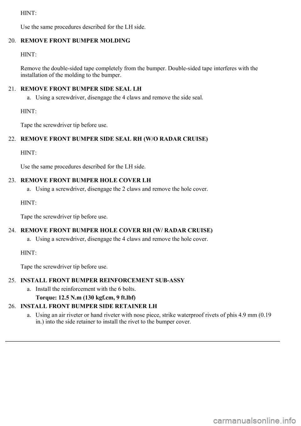
HINT:
Use the same procedures described for the LH side.
20.REMOVE FRONT BUMPER MOLDING
HINT:
Remove the double-sided tape completely from the bumper. Double-sided tape interferes with the
installation of the molding to the bumper.
21.REMOVE FRONT BUMPER SIDE SEAL LH
a. Using a screwdriver, disengage the 4 claws and remove the side seal.
HINT:
Tape the screwdriver tip before use.
22.REMOVE FRONT BUMPER SIDE SEAL RH (W/O RADAR CRUISE)
HINT:
Use the same procedures described for the LH side.
23.REMOVE FRONT BUMPER HOLE COVER LH
a. Using a screwdriver, disengage the 2 claws and remove the hole cover.
HINT:
Tape the screwdriver tip before use.
24.REMOVE FRONT BUMPER HOLE COVER RH (W/ RADAR CRUISE)
a. Using a screwdriver, disengage the 4 claws and remove the hole cover.
HINT:
Tape the screwdriver tip before use.
25.INSTALL FRONT BUMPER REINFORCEMENT SUB-ASSY
a. Install the reinforcement with the 6 bolts.
Torque: 12.5 N.m (130 kgf.cm, 9 ft.lbf)
26.INSTALL FRONT BUMPER SIDE RETAINER LH
a. Using an air riveter or hand riveter with nose piece, strike waterproof rivets of phis 4.9 mm (0.19
in.) into the side retainer to install the rivet to the bumper cover.
Page 3803 of 4500
20.REMOVE REAR BUMPER SIDE MOUNTING BRACKET LH
a. Remove the screw and bracket.
21.REMOVE REAR BUMPER SIDE MOUNTING BRACKET RH
a. Remove the screw and bracket.
22.REMOVE REAR BUMPER ARM SUPPORT REINFORCE SUB-ASSY LH
a. Remove the 2 bolts, nut and arm support.
23.REMOVE REAR BUMPER ARM SUPPORT REINFORCE SUB-ASSY RH
a. Remove the 2 bolts, nut and arm support.
24.REMOVE REAR BUMPER RETAINER LOWER LH
a. Remove the 3 screws and retainer lower.
25.REMOVE REAR BUMPER RETAINER LOWER RH
a. Remove the 3 screws and retainer lower.
26.REMOVE ULTRASONIC SENSOR NO. 1 (w/ CLEARANCE SONAR SYSTEM)
a. Remove the 4 retainers and 4 sensors.
27.REMOVE REAR BUMPER molding
HINT:
Remove the double-sided tape completely from the bumper. Double-sided tape interferes with the
installation of the molding to the bumper.
28.REMOVE REAR BUMPER SIDE RETAINER NO. 3 LH
a. Remove the 2 clips and side retainer.
29.REMOVE REAR BUMPER SIDE RETAINER NO. 3 RH
a. Remove the 2 clips and side retainer.
30.INSTALL REAR BUMPER ARM SUPPORT REINFORCE SUB-ASSY LH
a. Install the arm support with the 2 bolts and nut.
Torque: 20 N.m (200 kgf.cm, 15 ft.lbf)
31.INSTALL REAR BUMPER ARM SUPPORT REINFORCE SUB-ASSY RH
a. Install the arm support with the 2 bolts and nut.
Torque: 20 N.m (200 kgf.cm, 15 ft.lbf)
32.INSTALL REAR BUMPER REINFORCEMENT SUB-ASSY
a. Install the reinforcement with the 2 bolts and nut.
Torque: 20 N.m (200 kgf.cm, 15 ft.lbf)
33.INSTALL REAR BUMPER SIDE RETAINER LH
a. Using an air riveter or hand riveter with nose piece, strike waterproof rivets of phis 4.9 mm (0.19
in.) into the side retainer to install the rivet to the bumper cover.