Page 3915 of 4500
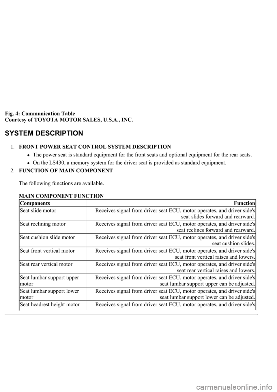
Fig. 4: Communication Table
Courtesy of TOYOTA MOTOR SALES, U.S.A., INC.
1.FRONT POWER SEAT CONTROL SYSTEM DESCRIPTION
The power seat is standard equipment for the front seats and optional equipment for the rear seats.
On the LS430, a memory system for the driver seat is provided as standard equipment.
2.FUNCTION OF MAIN COMPONENT
The following functions are available.
MAIN COMPONENT FUNCTION
ComponentsFunction
Seat slide motorReceives signal from driver seat ECU, motor operates, and driver side's
seat slides forward and rearward.
Seat reclining motorReceives signal from driver seat ECU, motor operates, and driver side's
seat reclines forward and rearward.
Seat cushion slide motorReceives signal from driver seat ECU, motor operates, and driver side's
seat cushion slides.
Seat front vertical motorReceives signal from driver seat ECU, motor operates, and driver side's
seat front vertical raises and lowers.
Seat rear vertical motorReceives signal from driver seat ECU, motor operates, and driver side's
seat rear vertical raises and lowers.
Seat lumbar support upper
motorReceives signal from driver seat ECU, motor operates, and driver side's
seat lumbar support upper can be adjusted.
Seat lumbar support lower
motorReceives signal from driver seat ECU, motor operates, and driver side's
seat lumbar support lower can be adjusted.
Seat headrest height motorReceives signal from driver seat ECU, motor operates, and driver side's
Page 3916 of 4500
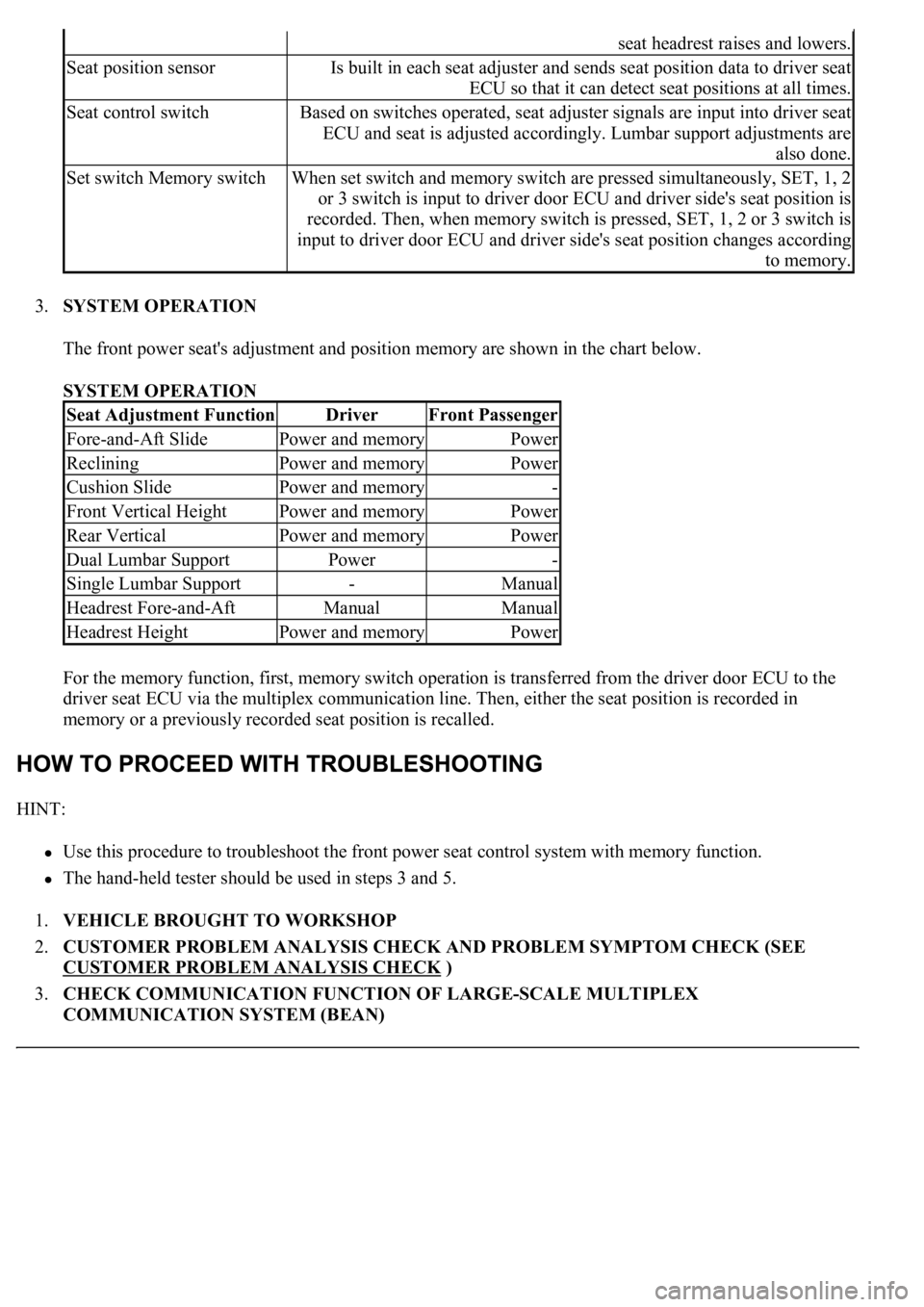
3.SYSTEM OPERATION
The front power seat's adjustment and position memory are shown in the chart below.
SYSTEM OPERATION
For the memory function, first, memory switch operation is transferred from the driver door ECU to the
driver seat ECU via the multiplex communication line. Then, either the seat position is recorded in
memory or a previously recorded seat position is recalled.
HINT:
Use this procedure to troubleshoot the front power seat control system with memory function.
<0037004b00480003004b0044005100470010004b0048004f0047000300570048005600570048005500030056004b00520058004f0047000300450048000300580056004800470003004c005100030056005700480053005600030016000300440051004700
030018001100030003[
1.VEHICLE BROUGHT TO WORKSHOP
2.CUSTOMER PROBLEM ANALYSIS CHECK AND PROBLEM SYMPTOM CHECK (SEE
CUSTOMER PROBLEM ANALYSIS CHECK
)
3.CHECK COMMUNICATION FUNCTION OF LARGE-SCALE MULTIPLEX
COMMUNICATION SYSTEM (BEAN)
seat headrest raises and lowers.
Seat position sensorIs built in each seat adjuster and sends seat position data to driver seat
ECU so that it can detect seat positions at all times.
Seat control switchBased on switches operated, seat adjuster signals are input into driver seat
ECU and seat is adjusted accordingly. Lumbar support adjustments are
also done.
Set switch Memory switchWhen set switch and memory switch are pressed simultaneously, SET, 1, 2
or 3 switch is input to driver door ECU and driver side's seat position is
recorded. Then, when memory switch is pressed, SET, 1, 2 or 3 switch is
input to driver door ECU and driver side's seat position changes according
to memory.
Seat Adjustment FunctionDriverFront Passenger
Fore-and-Aft SlidePower and memoryPower
RecliningPower and memoryPower
Cushion SlidePower and memory-
Front Vertical HeightPower and memoryPower
Rear VerticalPower and memoryPower
Dual Lumbar SupportPower-
Single Lumbar Support-Manual
Headrest Fore-and-AftManualManual
Headrest HeightPower and memoryPower
Page 3919 of 4500
Front power seat:
FRONT POWER SEAT - CUSTOMIZE PARAMETERS
1.INITIALIZE FRONT POWER SEAT CONTROL SYSTEM
a. The power seat ECU must be initialized under any of the following conditions.
The battery is disconnected.
The D/C cut fuse is replaced.
The power seat switch (power seat ECU) is replaced.
The power seat assy is removed from the vehicle.
b. Initialize the power seat ECU as follows.
1. Using the seat switches, fully slide the seat forward, fully recline the seatback forward, and
fully raise the seat cushion and headrest.
2. Using the seat switches, fully slide the seat rearward, fully recline the seatback rearward, and
fully lower the seat cushion and headrest.
Display (Item)DefaultContentsSetting
HEADREST CONTROLAVAILFunction that activates
physique compensation
headrest control when driver
seat is moved (sliding).NOT AVL/AVAIL
Page 3930 of 4500
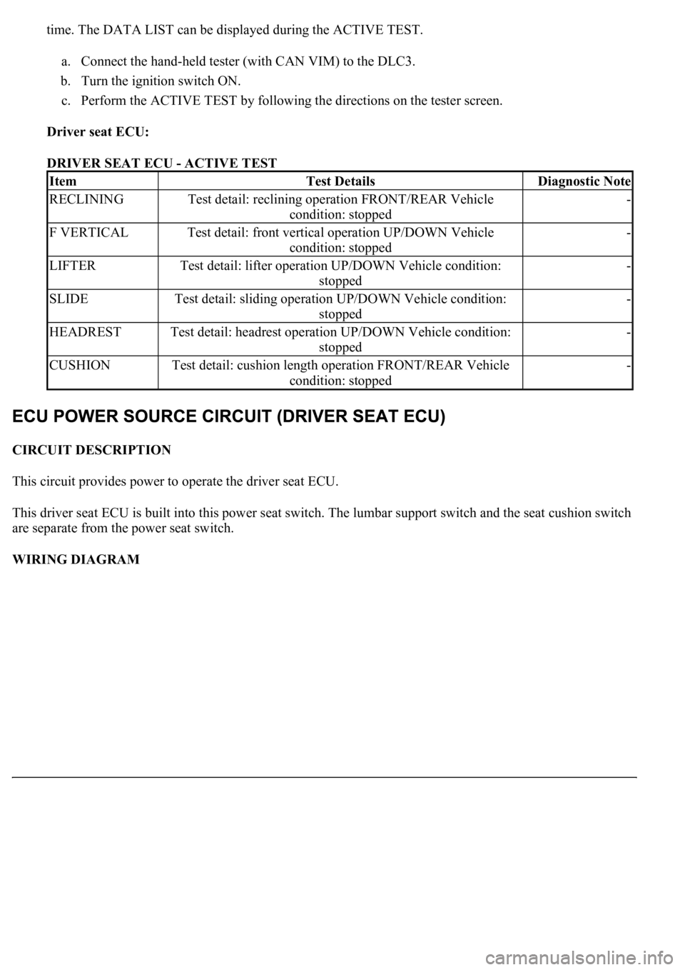
time. The DATA LIST can be displayed during the ACTIVE TEST.
a. Connect the hand-held tester (with CAN VIM) to the DLC3.
b. Turn the ignition switch ON.
c. Perform the ACTIVE TEST by following the directions on the tester screen.
Driver seat ECU:
DRIVER SEAT ECU - ACTIVE TEST
CIRCUIT DESCRIPTION
This circuit provides power to operate the driver seat ECU.
This driver seat ECU is built into this power seat switch. The lumbar support switch and the seat cushion switch
are separate from the power seat switch.
WIRING DIAGRAM
ItemTest DetailsDiagnostic Note
RECLININGTest detail: reclining operation FRONT/REAR Vehicle
condition: stopped-
F VERTICALTest detail: front vertical operation UP/DOWN Vehicle
condition: stopped-
LIFTERTest detail: lifter operation UP/DOWN Vehicle condition:
stopped-
SLIDETest detail: sliding operation UP/DOWN Vehicle condition:
stopped-
HEADRESTTest detail: headrest operation UP/DOWN Vehicle condition:
stopped-
CUSHIONTest detail: cushion length operation FRONT/REAR Vehicle
condition: stopped-
Page 3939 of 4500
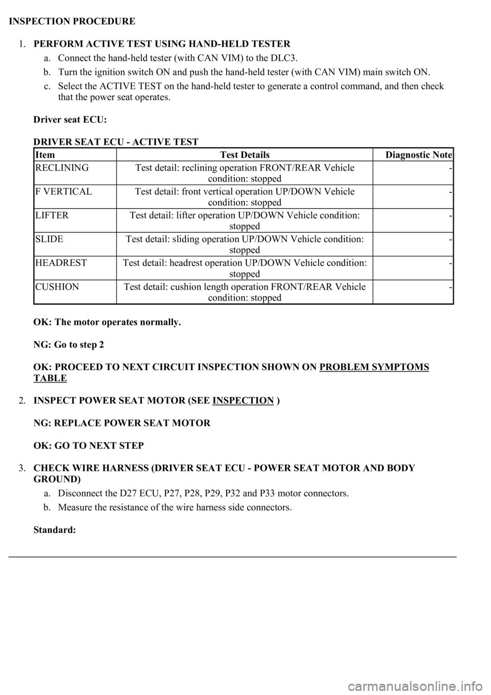
INSPECTION PROCEDURE
1.PERFORM ACTIVE TEST USING HAND-HELD TESTER
a. Connect the hand-held tester (with CAN VIM) to the DLC3.
b. Turn the ignition switch ON and push the hand-held tester (with CAN VIM) main switch ON.
c. Select the ACTIVE TEST on the hand-held tester to generate a control command, and then check
that the power seat operates.
Driver seat ECU:
DRIVER SEAT ECU - ACTIVE TEST
OK: The motor operates normally.
NG: Go to step 2
OK: PROCEED TO NEXT CIRCUIT INSPECTION SHOWN ON PROBLEM SYMPTOMS
TABLE
2.INSPECT POWER SEAT MOTOR (SEE INSPECTION
)
NG: REPLACE POWER SEAT MOTOR
OK: GO TO NEXT STEP
3.CHECK WIRE HARNESS (DRIVER SEAT ECU - POWER SEAT MOTOR AND BODY
GROUND)
a. Disconnect the D27 ECU, P27, P28, P29, P32 and P33 motor connectors.
b. Measure the resistance of the wire harness side connectors.
Standard:
ItemTest DetailsDiagnostic Note
RECLININGTest detail: reclining operation FRONT/REAR Vehicle
condition: stopped-
F VERTICALTest detail: front vertical operation UP/DOWN Vehicle
condition: stopped-
LIFTERTest detail: lifter operation UP/DOWN Vehicle condition:
stopped-
SLIDETest detail: sliding operation UP/DOWN Vehicle condition:
stopped-
HEADRESTTest detail: headrest operation UP/DOWN Vehicle condition:
stopped-
CUSHIONTest detail: cushion length operation FRONT/REAR Vehicle
condition: stopped-
Page 3949 of 4500
Fig. 27: Identifying D28 Driver Seat ECU Connector Terminals
Courtesy of TOYOTA MOTOR SALES, U.S.A., INC.
A: REPLACE FRONT SEAT HEADREST ADJUSTER
B: REPLACE FRONT POWER SEAT ADJUSTER
OK: PROCEED TO NEXT CIRCUIT INSPECTION SHOWN ON PROBLEM SYMPTOMS
TABLE
CIRCUIT DESCRIPTION
Pressing the lumbar switch activates the lumbar support motor.
Because the lumbar support switch is not connected to the driver seat ECU, pressing this switch does not
operate ECU operations such as the memory function.
WIRING DIAGRAM
Page 3966 of 4500
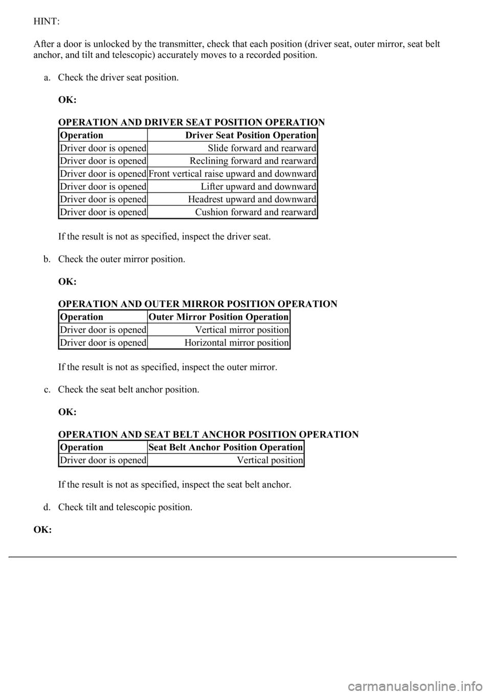
HINT:
After a door is unlocked by the transmitter, check that each position (driver seat, outer mirror, seat belt
anchor, and tilt and telescopic) accurately moves to a recorded position.
a. Check the driver seat position.
OK:
OPERATION AND DRIVER SEAT POSITION OPERATION
If the result is not as specified, inspect the driver seat.
b. Check the outer mirror position.
OK:
OPERATION AND OUTER MIRROR POSITION OPERATION
If the result is not as specified, inspect the outer mirror.
c. Check the seat belt anchor position.
OK:
OPERATION AND SEAT BELT ANCHOR POSITION OPERATION
If the result is not as specified, inspect the seat belt anchor.
d. Check tilt and telescopic position.
OK:
OperationDriver Seat Position Operation
Driver door is openedSlide forward and rearward
Driver door is openedReclining forward and rearward
Driver door is openedFront vertical raise upward and downward
Driver door is openedLifter upward and downward
Driver door is openedHeadrest upward and downward
Driver door is openedCushion forward and rearward
OperationOuter Mirror Position Operation
Driver door is openedVertical mirror position
Driver door is openedHorizontal mirror position
OperationSeat Belt Anchor Position Operation
Driver door is openedVertical position
Page 3967 of 4500
OPERATION AND TILT AND TELESCOPIC POSITION OPERATION
HINT:
*1: Wireless door lock control system
*2: Smart key system
If the result is not as specified, inspect the tilt and telescopic.
4.CHECK FRONT POWER SEAT FUNCTION
a. Check the basic functions.
1. Operate the power seat switches and check to make sure each seat function works:
Sliding
Front vertical
Lifter
Reclining
Lumbar support
Cushion sliding
Headrest
OperationTilt and Telescopic Position Operation
Key is inserted to the key cylinder*1 Engine switch is
pushed*2Vertical tilt position
Key is inserted to the key cylinder*1 Engine switch is
pushed*2Telescopic flexibility (lengthening and
shortening)