Page 2670 of 4500
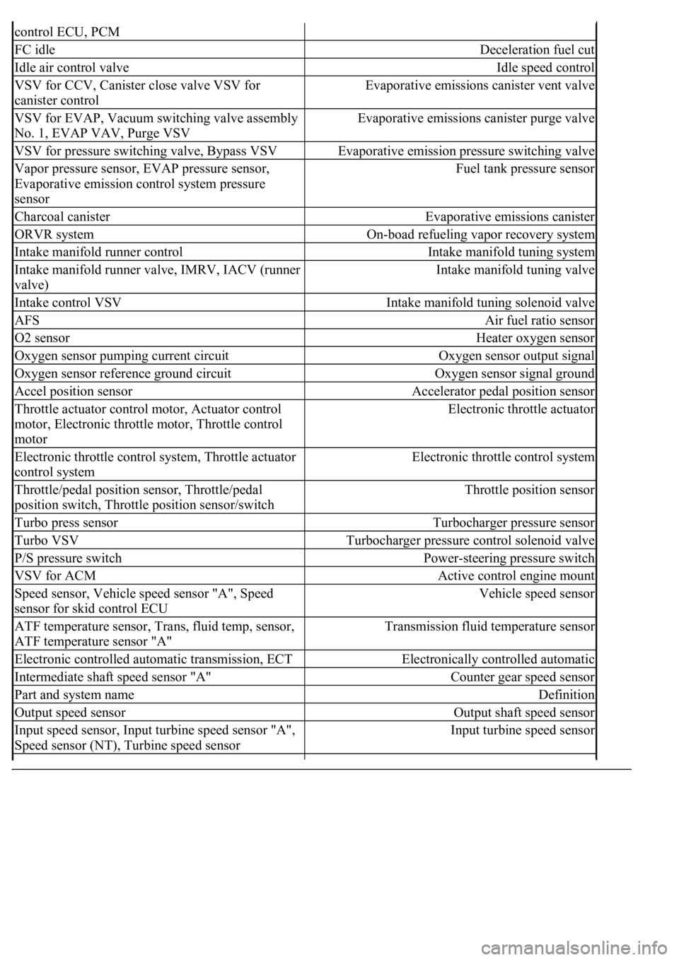
control ECU, PCM
FC idleDeceleration fuel cut
Idle air control valveIdle speed control
VSV for CCV, Canister close valve VSV for
canister controlEvaporative emissions canister vent valve
VSV for EVAP, Vacuum switching valve assembly
No. 1, EVAP VAV, Purge VSVEvaporative emissions canister purge valve
VSV for pressure switching valve, Bypass VSVEvaporative emission pressure switching valve
Vapor pressure sensor, EVAP pressure sensor,
Evaporative emission control system pressure
sensorFuel tank pressure sensor
Charcoal canisterEvaporative emissions canister
ORVR systemOn-boad refueling vapor recovery system
Intake manifold runner controlIntake manifold tuning system
Intake manifold runner valve, IMRV, IACV (runner
valve)Intake manifold tuning valve
Intake control VSVIntake manifold tuning solenoid valve
AFSAir fuel ratio sensor
O2 sensorHeater oxygen sensor
Oxygen sensor pumping current circuitOxygen sensor output signal
Oxygen sensor reference ground circuitOxygen sensor signal ground
Accel position sensorAccelerator pedal position sensor
Throttle actuator control motor, Actuator control
motor, Electronic throttle motor, Throttle control
motorElectronic throttle actuator
Electronic throttle control system, Throttle actuator
control systemElectronic throttle control system
Throttle/pedal position sensor, Throttle/pedal
position switch, Throttle position sensor/switchThrottle position sensor
Turbo press sensorTurbocharger pressure sensor
Turbo VSVTurbocharger pressure control solenoid valve
P/S pressure switchPower-steering pressure switch
VSV for ACMActive control engine mount
Speed sensor, Vehicle speed sensor "A", Speed
sensor for skid control ECUVehicle speed sensor
ATF temperature sensor, Trans, fluid temp, sensor,
ATF temperature sensor "A"Transmission fluid temperature sensor
Electronic controlled automatic transmission, ECTElectronically controlled automatic
Intermediate shaft speed sensor "A"Counter gear speed sensor
Part and system nameDefinition
Output speed sensorOutput shaft speed sensor
<002c00510053005800570003005600530048004800470003005600480051005600520055000f0003002c005100530058005700030057005800550045004c005100480003005600530048004800470003005600480051005600520055000300050024000500
0f0003[
Speed sensor (NT), Turbine speed sensorInput turbine speed sensor
Page 2927 of 4500
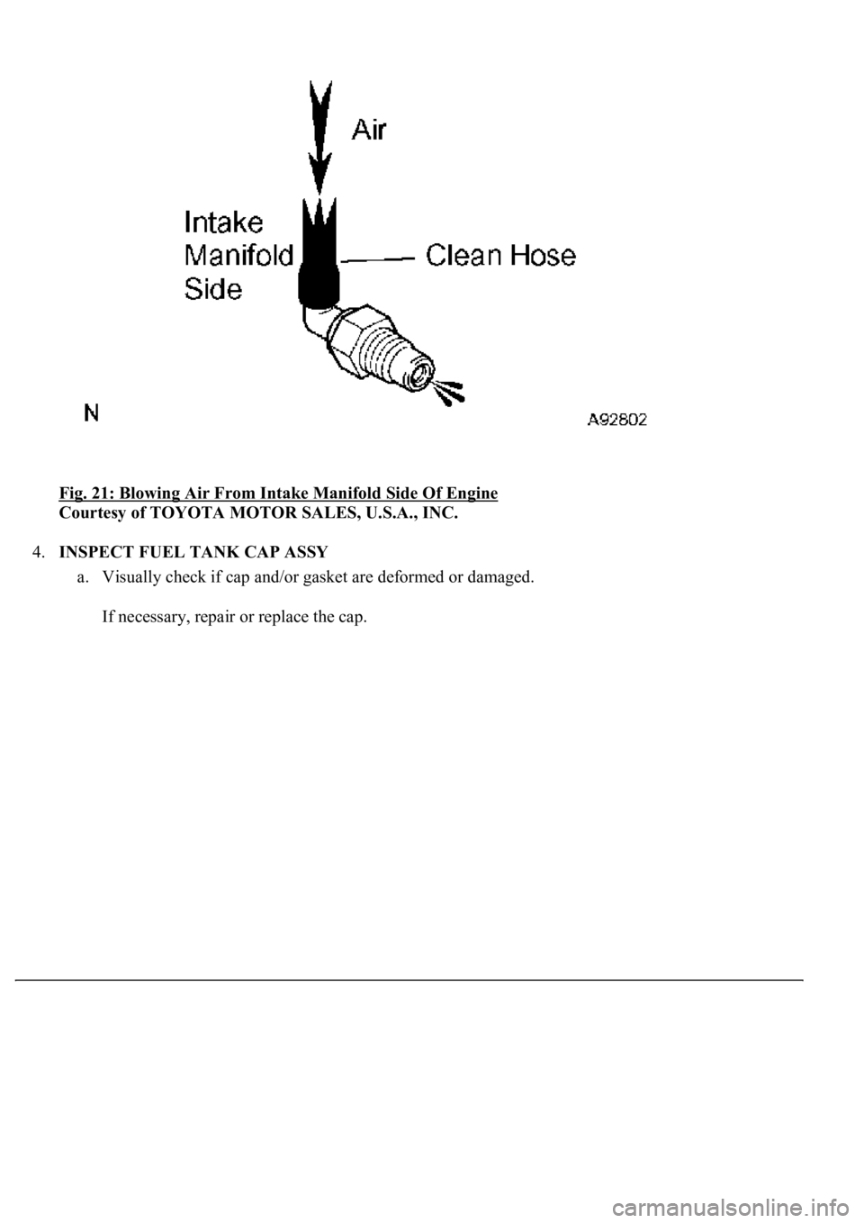
Fig. 21: Blowing Air From Intake Manifold Side Of Engine
Courtesy of TOYOTA MOTOR SALES, U.S.A., INC.
4.INSPECT FUEL TANK CAP ASSY
a. Visually check if cap and/or gasket are deformed or damaged.
If necessar
y, repair or replace the cap.
Page 2928 of 4500
Fig. 22: Inspecting Fuel Tank Cap Assy
Courtesy of TOYOTA MOTOR SALES, U.S.A., INC.
5.INSPECT PURGE VSV
a. Measure the purge VSV resistance.
Standard:
RESISTANCE CONDITION
If the result is not as specified, replace the pur
ge VSV.
Tester ConnectionSpecified Condition
1 - 226 to 30 ohms at 20°C (68°F)
1 - Body ground
2 - Body ground10 Mohms or higher
Page 4103 of 4500
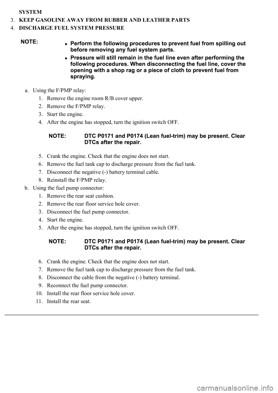
SYSTEM
3.KEEP GASOLINE AWAY FROM RUBBER AND LEATHER PARTS
4.DISCHARGE FUEL SYSTEM PRESSURE
a. Using the F/PMP relay:
1. Remove the engine room R/B cover upper.
2. Remove the F/PMP relay.
3. Start the engine.
4. After the engine has stopped, turn the ignition switch OFF.
5. Crank the engine. Check that the engine does not start.
6. Remove the fuel tank cap to discharge pressure from the fuel tank.
7. Disconnect the negative (-) battery terminal cable.
8. Reinstall the F/PMP relay.
b. Using the fuel pump connector:
1. Remove the rear seat cushion.
2. Remove the rear floor service hole cover.
3. Disconnect the fuel pump connector.
4. Start the engine.
5. After the engine has stopped, turn the ignition switch OFF.
6. Crank the engine. Check that the engine does not start.
7. Remove the fuel tank cap to discharge pressure from the fuel tank.
8. Disconnect the cable from the negative (-) battery terminal.
9. Reconnect the fuel pump connector.
10. Install the rear floor service hole cover.
11. Install the rear seat.
Page 4137 of 4500
REPLACEMENT
1.WORK FOR PREVENTING GASOLINE FROM SPILLING OUT (See PRECAUTION
)
2.DISCONNECT BATTERY NEGATIVE TERMINAL
3.DRAIN FUEL (See PRECAUTION
)
4.REMOVE SEPARATE TYPE REAR SEAT CUSHION ASSY LH (SEPARATED TYPE REAR
SEAT) (See OVERHAUL
)
5.REMOVE BENCH TYPE REAR SEAT CUSHION ASSY (FIXED TYPE REAR SEAT) (See
OVERHAUL
)
6.REMOVE REAR FLOOR SERVICE HOLE COVER NO.2
a. Remove the 3 cap nuts and service hole cover.
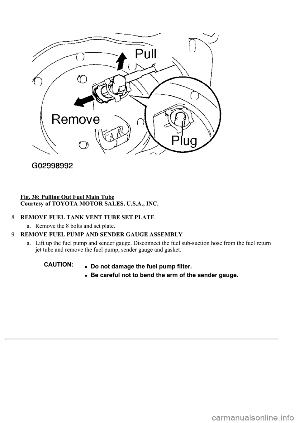
7.REMOVE FUEL TANK MAIN TUBE SUB-ASSY
Page 4139 of 4500
Fig. 38: Pulling Out Fuel Main Tube
Courtesy of TOYOTA MOTOR SALES, U.S.A., INC.
8.REMOVE FUEL TANK VENT TUBE SET PLATE
a. Remove the 8 bolts and set plate.
9.REMOVE FUEL PUMP AND SENDER GAUGE ASSEMBLY
a. Lift up the fuel pump and sender gauge. Disconnect the fuel sub-suction hose from the fuel return
<004d00480057000300570058004500480003004400510047000300550048005000520059004800030057004b00480003004900580048004f00030053005800500053000f00030056004800510047004800550003004a00440058004a004800030044005100
470003004a00440056004e00480057001100030003[
Page 4146 of 4500
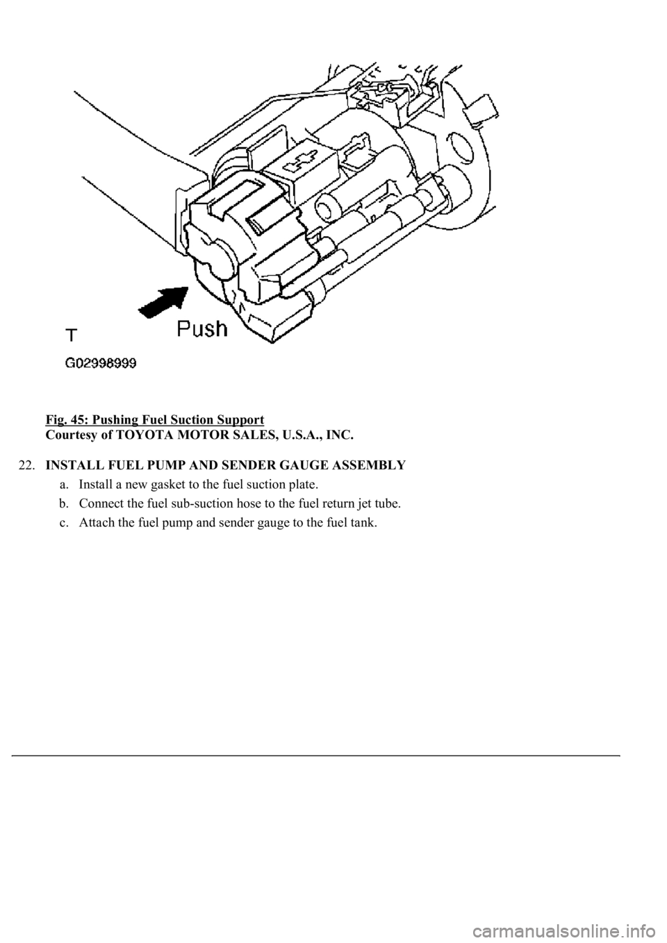
Fig. 45: Pushing Fuel Suction Support
Courtesy of TOYOTA MOTOR SALES, U.S.A., INC.
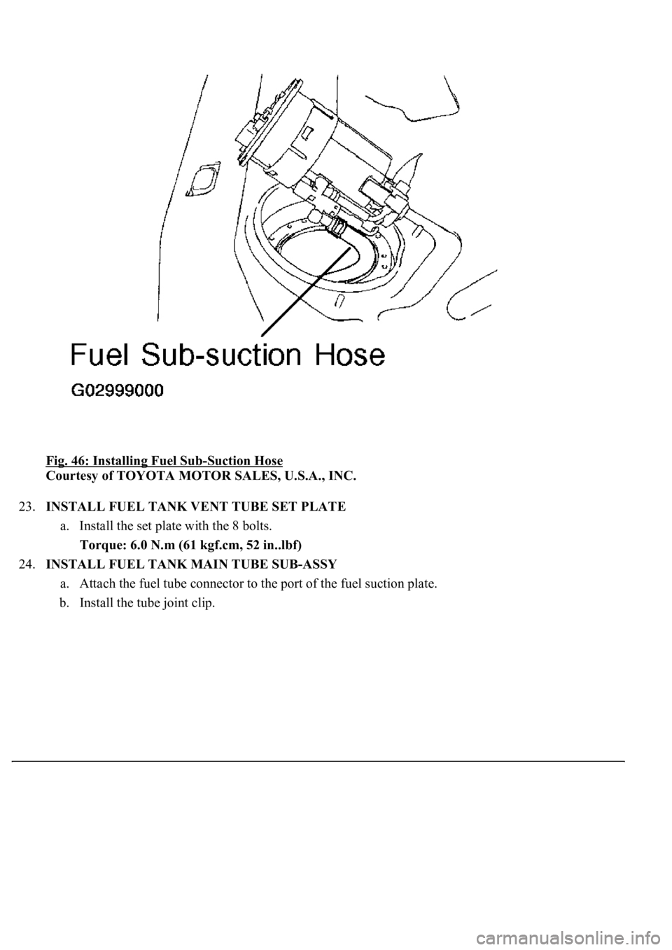
22.INSTALL FUEL PUMP AND SENDER GAUGE ASSEMBLY
a. Install a new gasket to the fuel suction plate.
b. Connect the fuel sub-suction hose to the fuel return jet tube.
c. Attach the fuel pump and sender
gauge to the fuel tank.
Page 4147 of 4500
Fig. 46: Installing Fuel Sub-Suction Hose
Courtesy of TOYOTA MOTOR SALES, U.S.A., INC.
23.INSTALL FUEL TANK VENT TUBE SET PLATE
a. Install the set plate with the 8 bolts.
Torque: 6.0 N.m (61 kgf.cm, 52 in..lbf)
24.INSTALL FUEL TANK MAIN TUBE SUB-ASSY
a. Attach the fuel tube connector to the port of the fuel suction plate.
b. Install the tube joint clip.