Page 25 of 4500
HINT:
<003a004b0048005100030057004b00480003005300440055004e004c0051004a0003004500550044004e00480003004c00560003004400530053004f004c0048004700030052005500030057004b00480003004f004800590048004f000300520049000300
57004b00480003004500550044004e004800030049004f0058[id is low, the BRAKE warning light
comes on.
b. When the ignition switch is turned to the ON position, check that the ABS warning light, TRAC
OFF indicator light, BRAKE warning light and SLIP indicator light come on for approximately 3
seconds.
HINT:
If the ECU was any stored DTCs, the ABS warning light, "VSC" is displayed on the multi-
information display and TRAC OFF indicator light come on.
If the indicator does not come on, inspect it the bulb is blown out, and also the wire harness
between the skid control ECU and the combination meter.
Page 131 of 4500
Fig. 98: Pedal Condition Reference Table
Courtesy of TOYOTA MOTOR SALES, U.S.A., INC.
NG: Go to step 6
HINT:
Check the stop lamp bulb as it may have burnt out.
OK:
2.INSPECT MULTIPLEX COMMUNICATION SYSTEM (SEE HOW TO PROCEED WITH
TROUBLESHOOTING )
a. Is DTC output Multiplex communication system?
Result:
DTC OUTPUT DESCRIPTION
B: REPAIR MULTIPLEX COMMUNICATION SYSTEM
A: Go to next step
3.CHECK HARNESS AND CONNECTOR (STP1 TERMINAL VOLTAGE OF DRIVER SIDE J/B
ECU)
a. Disconnect the driver side J/B ECU connector.
b. Measure the voltage according to the value (s) in the table below.
Standard:
TESTER CONNECTION SPECIFIED CONDITION
DTC is not outputA
TDC is outputB
Tester ConnectionSwitch ConditionSpecified Condition
D3-13 (STP1) - Body ground Brakepedal depressed8 to 14 V
D3-13 (STP1) - Body groundBrake pedal releasedBelow 1 V
Page 934 of 4500
Fig. 109: Removing Position Indicator Lens From Position Indicator Housing Upper
Courtesy of TOYOTA MOTOR SALES, U.S.A., INC.
28.REMOVE INDICATOR LAMP WIRE SUB-ASSY
a. Remove the indicator lamp wire sub-assy from the position indicator lens.
b. Remove the position indicator bulb from the indicator lamp wire sub-assy.
c. Remove the position indicator bulb cap from the position indicator bulb.
Page 952 of 4500
Fig. 126: Installing 3 bezel clips to position indicator housing upper
Courtesy of TOYOTA MOTOR SALES, U.S.A., INC.
41.INSTALL SHIFT LOCK RELEASE BUTTON
a. Install the shift lock release button and spring to the floor shift assy.
HINT:
Securely engage the claws.
Fig. 127: Installing Shift Lock Release Button And Spring To Floor Shift Assy
Courtesy of TOYOTA MOTOR SALES, U.S.A., INC.
42.INSTALL INDICATOR LAMP WIRE SUB-ASSY
a. Securely connect the 2 terminals of the indicator lamp wire harness to the transmission control
switch connector.
b. Install the position indicator lamp bulb to the indicator lamp wire sub-assy.
c. Install the position indicator bulb cap to the position indicator lamp bulb.
Page 1700 of 4500

Fig. 76: Identifying Seat Climate Control Blower Connector Terminals And Climate Control
Switch Connector Terminals
Courtesy of TOYOTA MOTOR SALES, U.S.A., INC.
NG: REPAIR OR REPLACE HARNESS AND CONNECTOR
OK: REPLACE SEAT CLIMATE CONTROL BLOWER (CLIMATE CONTROL ECU)
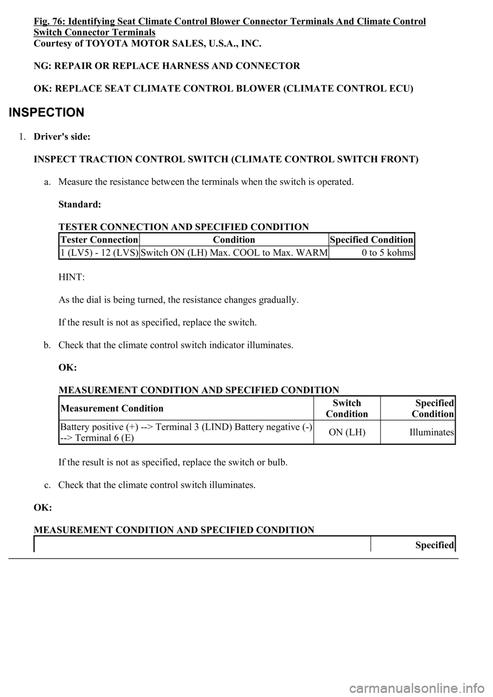
1.Driver's side:
INSPECT TRACTION CONTROL SWITCH (CLIMATE CONTROL SWITCH FRONT)
a. Measure the resistance between the terminals when the switch is operated.
Standard:
TESTER CONNECTION AND SPECIFIED CONDITION
HINT:
As the dial is being turned, the resistance changes gradually.
If the result is not as specified, replace the switch.
b. Check that the climate control switch indicator illuminates.
OK:
MEASUREMENT CONDITION AND SPECIFIED CONDITION
If the result is not as specified, replace the switch or bulb.
c. Check that the climate control switch illuminates.
OK:
MEASUREMENT CONDITION AND SPECIFIED CONDITION
Tester ConnectionConditionSpecified Condition
1 (LV5) - 12 (LVS)Switch ON (LH) Max. COOL to Max. WARM0 to 5 kohms
Measurement ConditionSwitch
ConditionSpecified
Condition
Battery positive (+) --> Terminal 3 (LIND) Battery negative (-)
--> Terminal 6 (E)ON (LH)Illuminates
Specified
Page 1701 of 4500
If the result is not as specified, replace the switch or bulb.
Measurement ConditionCondition
Battery positive (+) --> Terminal 20 (ILL+) Battery negative (-) --> Terminal 5
(ILL-)Illuminates
Page 1703 of 4500

Fig. 77: Identifying Traction Control Switch Connector Terminals -Driver Side (Climate Control
Switch Front)
Courtesy of TOYOTA MOTOR SALES, U.S.A., INC.
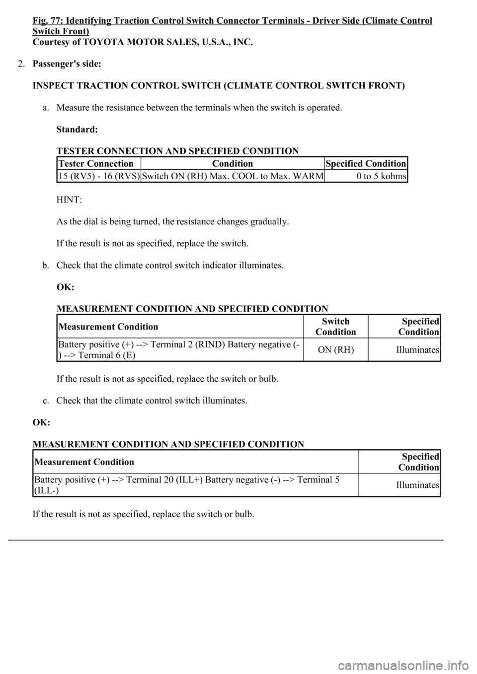
2.Passenger's side:
INSPECT TRACTION CONTROL SWITCH (CLIMATE CONTROL SWITCH FRONT)
a. Measure the resistance between the terminals when the switch is operated.
Standard:
TESTER CONNECTION AND SPECIFIED CONDITION
HINT:
As the dial is being turned, the resistance changes gradually.
If the result is not as specified, replace the switch.
b. Check that the climate control switch indicator illuminates.
OK:
MEASUREMENT CONDITION AND SPECIFIED CONDITION
If the result is not as specified, replace the switch or bulb.
c. Check that the climate control switch illuminates.
OK:
MEASUREMENT CONDITION AND SPECIFIED CONDITION
If the result is not as specified, replace the switch or bulb.
Tester ConnectionConditionSpecified Condition
15 (RV5) - 16 (RVS)Switch ON (RH) Max. COOL to Max. WARM0 to 5 kohms
Measurement ConditionSwitch
ConditionSpecified
Condition
Battery positive (+) --> Terminal 2 (RIND) Battery negative (-
) --> Terminal 6 (E)ON (RH)Illuminates
Measurement ConditionSpecified
Condition
Battery positive (+) --> Terminal 20 (ILL+) Battery negative (-) --> Terminal 5
(ILL-)Illuminates
Page 1711 of 4500

If the result is not as specified, replace the controller.
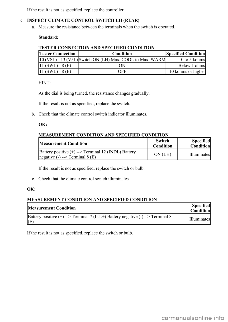
c.INSPECT CLIMATE CONTROL SWITCH LH (REAR)
a. Measure the resistance between the terminals when the switch is operated.
Standard:
TESTER CONNECTION AND SPECIFIED CONDITION
HINT:
As the dial is being turned, the resistance changes gradually.
If the result is not as specified, replace the switch.
b. Check that the climate control switch indicator illuminates.
OK:
MEASUREMENT CONDITION AND SPECIFIED CONDITION
If the result is not as specified, replace the switch or bulb.
c. Check that the climate control switch illuminates.
OK:
MEASUREMENT CONDITION AND SPECIFIED CONDITION
If the result is not as specified, replace the switch or bulb.
Tester ConnectionConditionSpecified Condition
10 (VSL) - 13 (V5L)Switch ON (LH) Max. COOL to Max. WARM0 to 5 kohms
11 (SWL) - 8 (E)ONBelow 1 ohms
11 (SWL) - 8 (E)OFF10 kohms or higher
Measurement ConditionSwitch
ConditionSpecified
Condition
Battery positive (+) --> Terminal 12 (INDL) Battery
negative (-) --> Terminal 8 (E)ON (LH)Illuminates
Measurement ConditionSpecified
Condition
Battery positive (+) --> Terminal 7 (ILL+) Battery negative (-) --> Terminal 8
(E)Illuminates