Page 1713 of 4500
Courtesy of TOYOTA MOTOR SALES, U.S.A., INC.
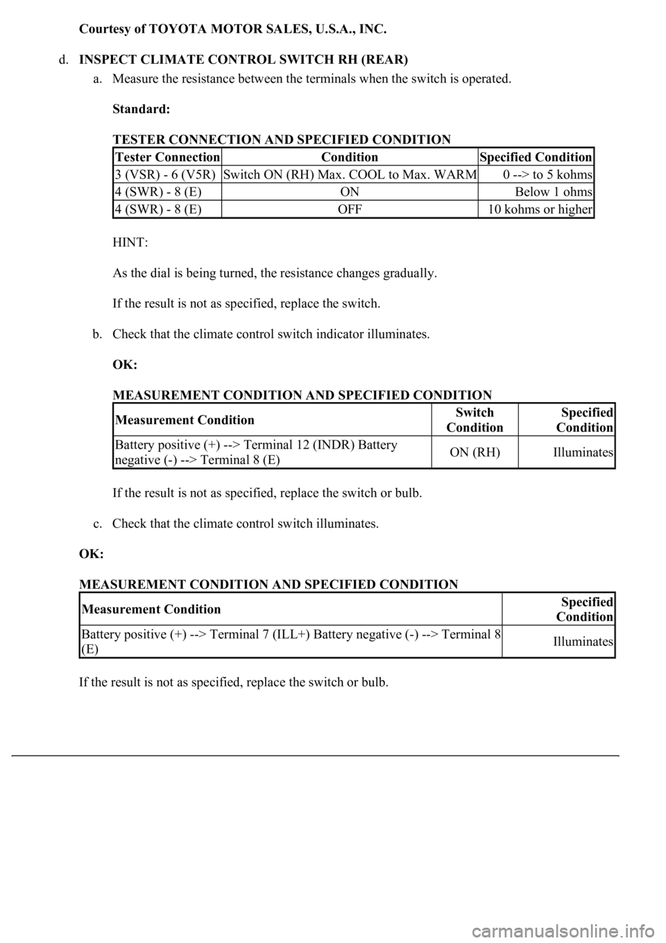
d.INSPECT CLIMATE CONTROL SWITCH RH (REAR)
a. Measure the resistance between the terminals when the switch is operated.
Standard:
TESTER CONNECTION AND SPECIFIED CONDITION
HINT:
As the dial is being turned, the resistance changes gradually.
If the result is not as specified, replace the switch.
b. Check that the climate control switch indicator illuminates.
OK:
MEASUREMENT CONDITION AND SPECIFIED CONDITION
If the result is not as specified, replace the switch or bulb.
c. Check that the climate control switch illuminates.
OK:
MEASUREMENT CONDITION AND SPECIFIED CONDITION
If the result is not as specified, replace the switch or bulb.
Tester ConnectionConditionSpecified Condition
3 (VSR) - 6 (V5R)Switch ON (RH) Max. COOL to Max. WARM0 --> to 5 kohms
4 (SWR) - 8 (E)ONBelow 1 ohms
4 (SWR) - 8 (E)OFF10 kohms or higher
Measurement ConditionSwitch
ConditionSpecified
Condition
Battery positive (+) --> Terminal 12 (INDR) Battery
negative (-) --> Terminal 8 (E)ON (RH)Illuminates
Measurement ConditionSpecified
Condition
Battery positive (+) --> Terminal 7 (ILL+) Battery negative (-) --> Terminal 8
(E)Illuminates
Page 2774 of 4500
Fig. 93: Tester Connection Reference Chart
Courtesy of TOYOTA MOTOR SALES, U.S.A., INC.
NG: REPAIR OR REPLACE HARNESS OR CONNECTOR (See ELECTRONIC CIRCUIT
INSPECTION PROCEDURE )
OK: REPLACE ECM (See REPLACEMENT
)
3.INSPECT SHIFT SOLENOID VALVE (SL1)
a. Remove the shift solenoid valve SL1.
b. Measure the resistance according to the value(s) in the table below.
Standard:
SHIFT SOLENOID VALVE (SL1) - RESISTANCE TABLE
c. Connect the positive (+) lead with a 21 W bulb to terminal 2 and the negative (-) lead to terminal 1
of the solenoid valve connector, then check the movement of the valve.
OK:
The solenoid makes an operating noise.
Tester ConnectionSpecified Condition 20°C (68°F)
1 - 25.0 to 5.6 ohms
Page 2809 of 4500
Fig. 117: Inspecting Shift Solenoid Valve (S4)
Courtesy of TOYOTA MOTOR SALES, U.S.A., INC.
NG: REPLACE SHIFT SOLENOID VALVE (S4)
OK: Go to next step
4.INSPECT SHIFT SOLENOID VALVE (SL2)
a. Remove the shift solenoid valve SL2.
b. Measure the resistance according to the value(s) in the table below.
Standard:
SHIFT SOLENOID VALVE (SL2) - RESISTANCE TABLE
c. Connect the positive (+) lead with a 21 W bulb to terminal 2 and the negative (-) lead to terminal 1
of the solenoid valve connector, then check the movement of the valve.
OK:
Tester ConnectionSpecified Condition 20°C (68°F)
1 - 25.0 to 5.6 ohms
Page 2816 of 4500
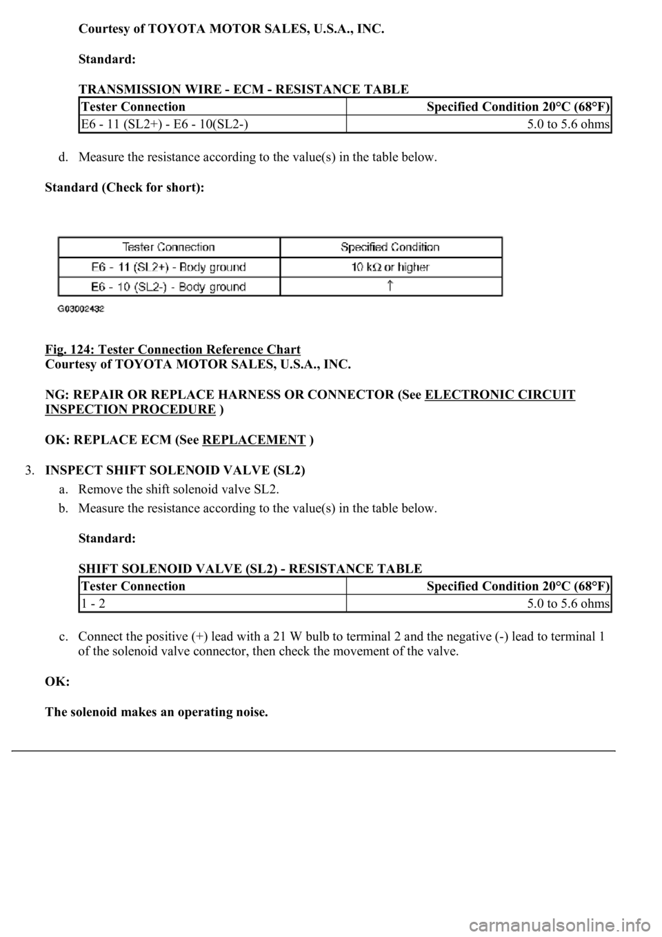
Courtesy of TOYOTA MOTOR SALES, U.S.A., INC.
Standard:
TRANSMISSION WIRE - ECM - RESISTANCE TABLE
d. Measure the resistance according to the value(s) in the table below.
Standard (Check for short):
Fig. 124: Tester Connection Reference Chart
Courtesy of TOYOTA MOTOR SALES, U.S.A., INC.
NG: REPAIR OR REPLACE HARNESS OR CONNECTOR (See ELECTRONIC CIRCUIT
INSPECTION PROCEDURE )
OK: REPLACE ECM (See REPLACEMENT
)
3.INSPECT SHIFT SOLENOID VALVE (SL2)
a. Remove the shift solenoid valve SL2.
b. Measure the resistance according to the value(s) in the table below.
Standard:
SHIFT SOLENOID VALVE (SL2) - RESISTANCE TABLE
c. Connect the positive (+) lead with a 21 W bulb to terminal 2 and the negative (-) lead to terminal 1
of the solenoid valve connector, then check the movement of the valve.
OK:
The solenoid makes an operating noise.
Tester ConnectionSpecified Condition 20°C (68°F)
E6 - 11 (SL2+) - E6 - 10(SL2-)5.0 to 5.6 ohms
Tester ConnectionSpecified Condition 20°C (68°F)
1 - 25.0 to 5.6 ohms
Page 2860 of 4500
b. Turn the ignition switch to the ON position and push the hand-held tester main switch ON.
c. Select the item "DIAGNOSIS/ENHANCED OBD II/DTC INFO/CURRENT CODES".
d. Read the DTCs using the hand-held tester.
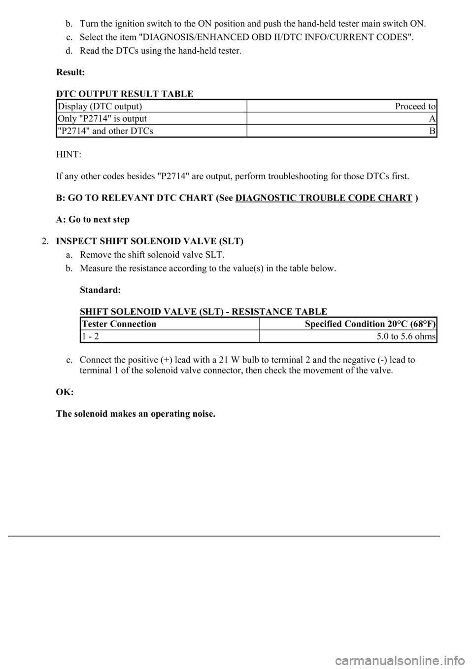
Result:
DTC OUTPUT RESULT TABLE
HINT:
If any other codes besides "P2714" are output, perform troubleshooting for those DTCs first.
B: GO TO RELEVANT DTC CHART (See DIAGNOSTIC TROUBLE CODE CHART
)
A: Go to next step
2.INSPECT SHIFT SOLENOID VALVE (SLT)
a. Remove the shift solenoid valve SLT.
b. Measure the resistance according to the value(s) in the table below.
Standard:
SHIFT SOLENOID VALVE (SLT) - RESISTANCE TABLE
c. Connect the positive (+) lead with a 21 W bulb to terminal 2 and the negative (-) lead to
terminal 1 of the solenoid valve connector, then check the movement of the valve.
OK:
The solenoid makes an operating noise.
Display (DTC output)Proceed to
Only "P2714" is outputA
"P2714" and other DTCsB
Tester ConnectionSpecified Condition 20°C (68°F)
1 - 25.0 to 5.6 ohms
Page 2867 of 4500
Fig. 171: Tester Connection Reference Chart
Courtesy of TOYOTA MOTOR SALES, U.S.A., INC.
NG: REPAIR OR REPLACE HARNESS OR CONNECTOR (See ELECTRONIC CIRCUIT
INSPECTION PROCEDURE )
OK: REPLACE ECM (See REPLACEMENT
)
3.INSPECT SHIFT SOLENOID VALVE (SLT)
a. Remove the shift solenoid valve (SLT).
b. Measure the resistance according to the value(s) in the table below.
Standard:
SHIFT SOLENOID VALVE (SLT) - RESISTANCE TABLE
c. Connect the positive (+) lead with a 21 W bulb to terminal 2 and the negative (-) lead to terminal 1
of the solenoid valve connector, then check the movement of the valve.
OK:
The solenoid makes an operating noise.
Tester ConnectionSpecified Condition 20°C (68°F)
1 - 25.0 to 5.6 ohms
Page 2877 of 4500
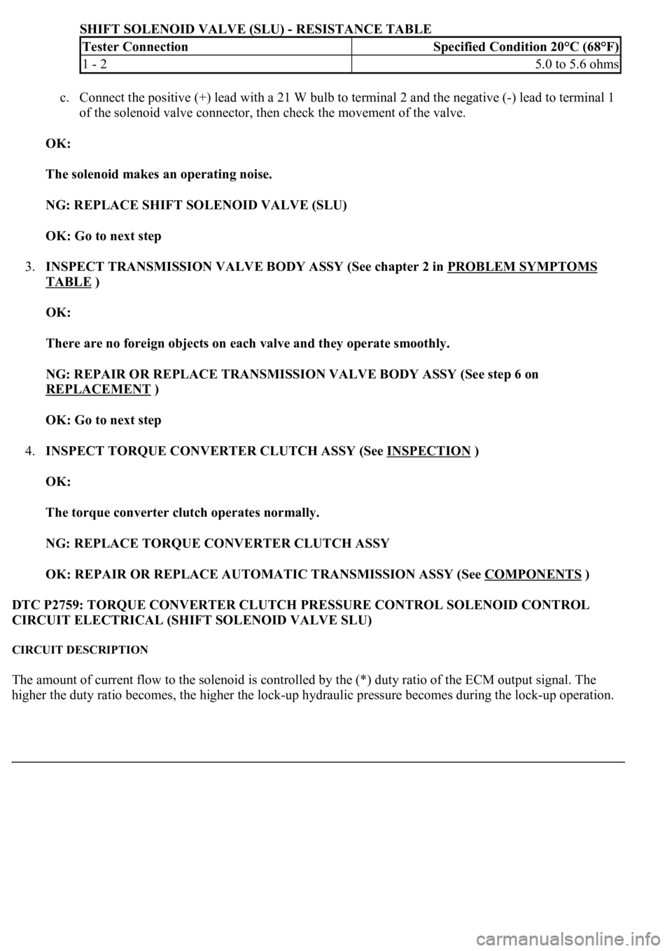
SHIFT SOLENOID VALVE (SLU) - RESISTANCE TABLE
c. Connect the positive (+) lead with a 21 W bulb to terminal 2 and the negative (-) lead to terminal 1
of the solenoid valve connector, then check the movement of the valve.
OK:
The solenoid makes an operating noise.
NG: REPLACE SHIFT SOLENOID VALVE (SLU)
OK: Go to next step
3.INSPECT TRANSMISSION VALVE BODY ASSY (See chapter 2 in PROBLEM SYMPTOMS
TABLE )
OK:
There are no foreign objects on each valve and they operate smoothly.
NG: REPAIR OR REPLACE TRANSMISSION VALVE BODY ASSY (See step 6 on
REPLACEMENT
)
OK: Go to next step
4.INSPECT TORQUE CONVERTER CLUTCH ASSY (See INSPECTION
)
OK:
The torque converter clutch operates normally.
NG: REPLACE TORQUE CONVERTER CLUTCH ASSY
OK: REPAIR OR REPLACE AUTOMATIC TRANSMISSION ASSY (See COMPONENTS
)
DTC P2759: TORQUE CONVERTER CLUTCH PRESSURE CONTROL SOLENOID CONTROL
CIRCUIT ELECTRICAL (SHIFT SOLENOID VALVE SLU)
CIRCUIT DESCRIPTION
The amount of current flow to the solenoid is controlled by the (*) duty ratio of the ECM output signal. The
hi
gher the duty ratio becomes, the higher the lock-up hydraulic pressure becomes during the lock-up operation.
Tester ConnectionSpecified Condition 20°C (68°F)
1 - 25.0 to 5.6 ohms
Page 2883 of 4500
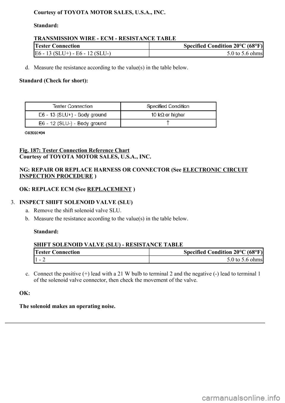
Courtesy of TOYOTA MOTOR SALES, U.S.A., INC.
Standard:
TRANSMISSION WIRE - ECM - RESISTANCE TABLE
d. Measure the resistance according to the value(s) in the table below.
Standard (Check for short):
Fig. 187: Tester Connection Reference Chart
Courtesy of TOYOTA MOTOR SALES, U.S.A., INC.
NG: REPAIR OR REPLACE HARNESS OR CONNECTOR (See ELECTRONIC CIRCUIT
INSPECTION PROCEDURE )
OK: REPLACE ECM (See REPLACEMENT
)
3.INSPECT SHIFT SOLENOID VALVE (SLU)
a. Remove the shift solenoid valve SLU.
b. Measure the resistance according to the value(s) in the table below.
Standard:
SHIFT SOLENOID VALVE (SLU) - RESISTANCE TABLE
c. Connect the positive (+) lead with a 21 W bulb to terminal 2 and the negative (-) lead to terminal 1
of the solenoid valve connector, then check the movement of the valve.
OK:
The solenoid makes an operating noise.
Tester ConnectionSpecified Condition 20°C (68°F)
E6 - 13 (SLU+) - E6 - 12 (SLU-)5.0 to 5.6 ohms
Tester ConnectionSpecified Condition 20°C (68°F)
1 - 25.0 to 5.6 ohms