Page 572 of 4500
Fig. 90: Identifying Air Sus Relay Location
Courtesy of TOYOTA MOTOR SALES, U.S.A., INC.
NG: REPAIR OR REPLACE HARNESS OR CONNECTOR
OK: REPLACE SUSPENSION CONTROL ECU (SEE REPLACEMENT
)
CIRCUIT DESCRIPTION
The signal from the suspension control ECU turns on the AIR SUS relay. At that time, battery voltage is input
to the height control compressor motor through the AIR SUS relay. The height control compressor motor starts.
<0029004c004a00110003001c0014001d0003002700370026000300260014001a001700150003002700480057004800460057004c0051004a00030026005200510047004c0057004c005200510003002400510047000300370055005200580045004f004800
030024005500480044[
Page 718 of 4500

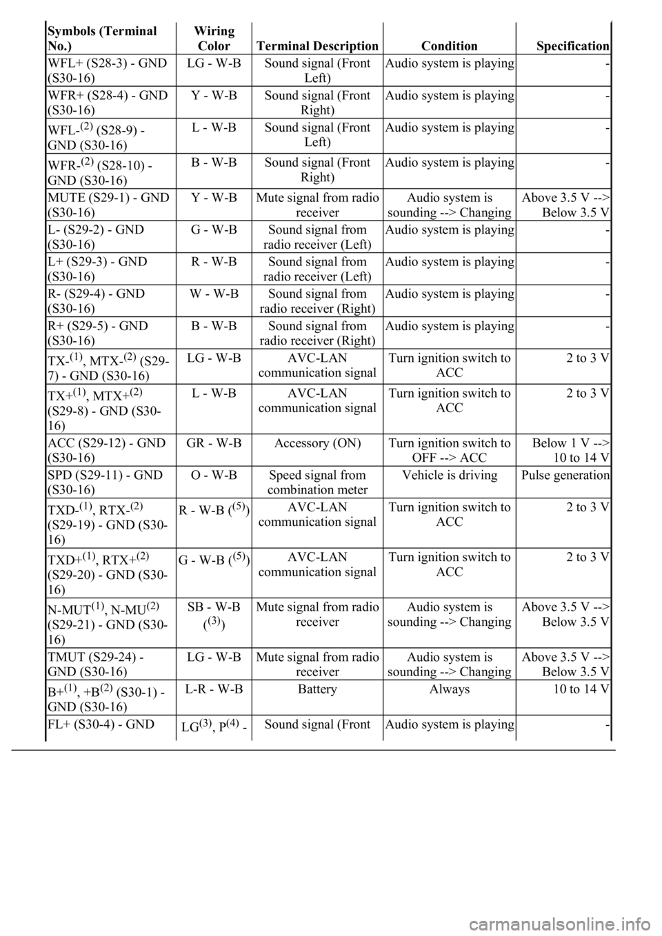
Symbols (Terminal
No.)Wiring
Color
Terminal DescriptionConditionSpecification
WFL+ (S28-3) - GND
(S30-16)LG - W-BSound signal (Front
Left)Audio system is playing-
WFR+ (S28-4) - GND
(S30-16)Y - W-BSound signal (Front
Right)Audio system is playing-
WFL-(2) (S28-9) -
GND (S30-16)L - W-BSound signal (Front
Left)Audio system is playing-
WFR-(2) (S28-10) -
GND (S30-16)B - W-BSound signal (Front
Right)Audio system is playing-
MUTE (S29-1) - GND
(S30-16)Y - W-BMute signal from radio
receiverAudio system is
sounding --> ChangingAbove 3.5 V -->
Below 3.5 V
L- (S29-2) - GND
(S30-16)G - W-BSound signal from
radio receiver (Left)Audio system is playing-
L+ (S29-3) - GND
(S30-16)R - W-BSound signal from
radio receiver (Left)Audio system is playing-
R- (S29-4) - GND
(S30-16)W - W-BSound signal from
radio receiver (Right)Audio system is playing-
R+ (S29-5) - GND
(S30-16)B - W-BSound signal from
radio receiver (Right)Audio system is playing-
TX-(1), MTX-(2) (S29-
7) - GND (S30-16)LG - W-BAVC-LAN
communication signalTurn ignition switch to
ACC2 to 3 V
TX+(1), MTX+(2)
(S29-8) - GND (S30-
16)L - W-BAVC-LAN
communication signalTurn ignition switch to
ACC2 to 3 V
ACC (S29-12) - GND
(S30-16)GR - W-BAccessory (ON)Turn ignition switch to
OFF --> ACCBelow 1 V -->
10 to 14 V
SPD (S29-11) - GND
(S30-16)O - W-BSpeed signal from
combination meterVehicle is drivingPulse generation
TXD-(1), RTX-(2)
(S29-19) - GND (S30-
16)R - W-B ((5))AVC-LAN
communication signalTurn ignition switch to
ACC2 to 3 V
TXD+(1), RTX+(2)
(S29-20) - GND (S30-
16)G - W-B ((5))AVC-LAN
communication signalTurn ignition switch to
ACC2 to 3 V
N-MUT(1), N-MU(2)
(S29-21) - GND (S30-
16)SB - W-B
(
(3))
Mute signal from radio
receiverAudio system is
sounding --> ChangingAbove 3.5 V -->
Below 3.5 V
TMUT (S29-24) -
GND (S30-16)LG - W-BMute signal from radio
receiverAudio system is
sounding --> ChangingAbove 3.5 V -->
Below 3.5 V
B+(1), +B(2) (S30-1) -
GND (S30-16)L-R - W-BBatteryAlways10 to 14 V
FL+ (S30-4) - GND LG(3), P(4) - Sound signal (Front Audio system is playing-
Page 720 of 4500

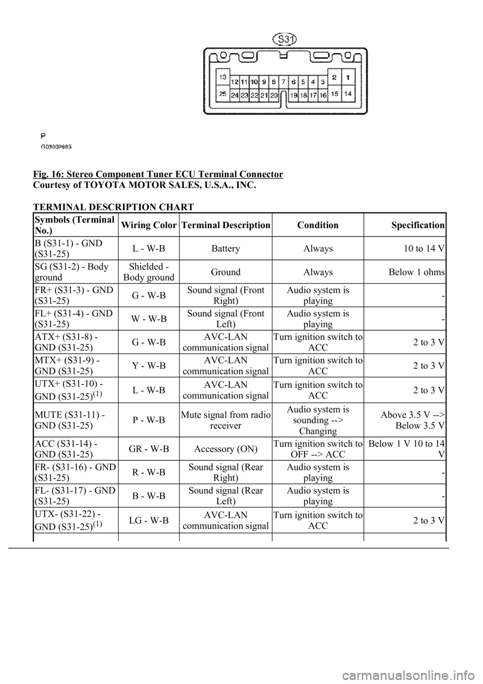
Fig. 16: Stereo Component Tuner ECU Terminal Connector
Courtesy of TOYOTA MOTOR SALES, U.S.A., INC.
TERMINAL DESCRIPTION CHART
Symbols (Terminal
No.)Wiring ColorTerminal DescriptionConditionSpecification
B (S31-1) - GND
(S31-25)L - W-BBatteryAlways10 to 14 V
SG (S31-2) - Body
groundShielded -
Body groundGroundAlwaysBelow 1 ohms
FR+ (S31-3) - GND
(S31-25)G - W-BSound signal (Front
Right)Audio system is
playing-
FL+ (S31-4) - GND
(S31-25)W - W-BSound signal (Front
Left)Audio system is
playing-
ATX+ (S31-8) -
GND (S31-25)G - W-BAVC-LAN
communication signalTurn ignition switch to
ACC2 to 3 V
MTX+ (S31-9) -
GND (S31-25)Y - W-BAVC-LAN
communication signalTurn ignition switch to
ACC2 to 3 V
UTX+ (S31-10) -
GND (S31-25)
(1)L - W-BAVC-LAN
communication signalTurn ignition switch to
ACC2 to 3 V
MUTE (S31-11) -
GND (S31-25)P - W-BMute signal from radio
receiverAudio system is
sounding -->
ChangingAbove 3.5 V -->
Below 3.5 V
ACC (S31-14) -
GND (S31-25)GR - W-BAccessory (ON)Turn ignition switch to
OFF --> ACCBelow 1 V 10 to 14
V
FR- (S31-16) - GND
(S31-25)R - W-BSound signal (Rear
Right)Audio system is
playing-
FL- (S31-17) - GND
(S31-25)B - W-BSound signal (Rear
Left)Audio system is
playing-
UTX- (S31-22) -
GND (S31-25)
(1)LG - W-BAVC-LAN
communication signalTurn ignition switch to
ACC2 to 3 V
Page 721 of 4500
4.AUDIO AND REAR A/C CONTROL SW
Fig. 17: Audio And Rear A/C Control SW ECU Terminal Connector
Courtesy of TOYOTA MOTOR SALES, U.S.A., INC.
TERMINAL DESCRIPTION CHART
ATX- (S31-20) -
GND (S31-25)R - W-BAVC-LAN
communication signalTurn ignition switch to
ACC2 to 3 V
MTX- (S31-21) -
GND (S31-25)B - W-BAVC-LAN
communication signalTurn ignition switch to
ACC2 to 3 V
GND (S31-25) -
Body groundW-B - Body
groundGroundAlwaysBelow 1 ohms
(1)w/ LEXUS Navigation System
Symbols (Terminal
No.)Wiring
ColorTerminal DescriptionConditionSpecification
Page 722 of 4500

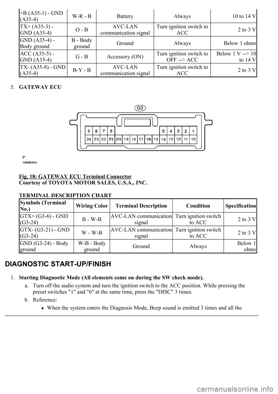
5.GATEWAY ECU
Fig. 18: GATEWAY ECU Terminal Connector
Courtesy of TOYOTA MOTOR SALES, U.S.A., INC.
TERMINAL DESCRIPTION CHART
1.Starting Diagnostic Mode (All elements come on during the SW check mode).
a. Turn off the audio system and turn the ignition switch to the ACC position. While pressing the
preset switches "1" and "6" at the same time, press the "DISC" 3 times.
b. Reference:
<003a004b0048005100030057004b004800030056005c0056005700480050000300480051005700480055005600030057004b004800030027004c0044004a005100520056004c005600030030005200470048000f0003002500480048005300030056005200
58005100470003004c0056000300480050004c005700570048[d 3 times and all the
+B (A35-1) - GND
(A35-4)W-R - BBatteryAlways10 to 14 V
TX+ (A35-3) -
GND (A35-4)O - BAVC-LAN
communication signalTurn ignition switch to
ACC2 to 3 V
GND (A35-4) -
Body groundB - Body
groundGroundAlwaysBelow 1 ohms
ACC (A35-5) -
GND (A35-4)G - BAccessory (ON)Turn ignition switch to
OFF --> ACCBelow 1 V --> 10
to 14 V
TX- (A35-8) - GND
(A35-4)B-Y - BAVC-LAN
communication signalTurn ignition switch to
ACC2 to 3 V
Symbols (Terminal
No.)Wiring ColorTerminal DescriptionConditionSpecification
GTX+ (G3-6) - GND
(G3-24)B - W-BAVC-LAN communication
signalTurn ignition switch
to ACC2 to 3 V
GTX- (G3-21) - GND
(G3-24)W - W-BAVC-LAN communication
signalTurn ignition switch
to ACC2 to 3 V
GND (G3-24) - Body
groundW-B - Body
groundGroundAlwaysBelow 1
ohms
Page 749 of 4500

NG: REPLACE THE CD
OK: Go to next step
3.CHECK RADIO RECEIVER ASSY
a. Insert another CD and check if it is ejected.
OK: The disc is ejected.
NG: REPLACE RADIO RECEIVER ASSY (SEE REPLACEMENT
)
OK: NORMAL OPERATION
INSPECTION PROCEDURE
1.CHECK SPEAKERS
a. Check the speaker unit installed condition.
1. Check that each speaker is securely installed.
OK: The problem goes away.
HINT:
The radio has a noise prevention function to reduce noise when listening to the radio. If a loud noise
occurs, check whether the ground at the antenna mounting base and the noise prevention unit are installed
and wired correctly.
NOISE CONDITION CHART
Noise ConditionsNoise Source
Depressing the accelerator pedal makes the noise louder. However, the noise
stops immediately when the engine is stopped.Alternator
Noise occurs while the A/C or heater is in operation.Blower motor
Noise can be heard during sudden acceleration on an unpaved road, or after the
ignition switch is turned ON.Fuel pump
Noise can be heard when the horn is pressed and released, or held down
continuously.Horn
<00340058004c00480057000300510052004c0056004800030046004400510003004500480003004b00480044005500470003005a004b004c004f004800030057004b0048000300480051004a004c0051004800030055005800510056000f00030045005800
570003005600570052005300560003005a004b004800510003[the engine is
stopped.Ignition
Noise can be heard when the turn signal blinks.Flasher
Noise can be heard while window washer is in operation.Washer
Noise can be heard while the engine is running and continues after it is stopped.Water temperature
sensor
Noise can be heard while the wiper system is in operation.Wiper
Page 784 of 4500
Fig. 66: Identifying Stereo Components Tuner Connector
Courtesy of TOYOTA MOTOR SALES, U.S.A., INC.
OK: PROCEED TO NEXT CIRCUIT INSPECTION SHOWN ON PROBLEM SYMPTOMS
TABLE
CIRCUIT DESCRIPTION
This circuit is necessary for the stereo component amplifier assy for the ASL (Auto Sound Leveliser). Speed
signals are received from the combination meter.
The ASL function automatically adjusts the sound data in order to enable to hear the clear audio sound even
when the vehicle noise is increased (as vehicle noise increased, the volume is turned up etc.)
Standard System: Using speed signals and a microphone for the ASL built into the stereo component amplifier
assy.
Mark Levinson System: Using speed signals.
Page 985 of 4500

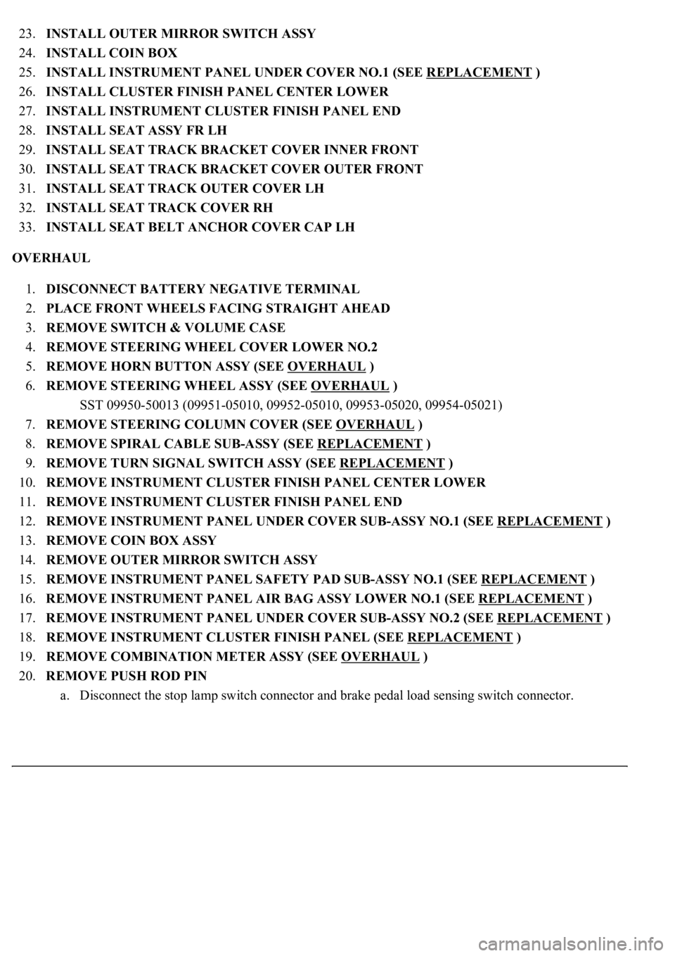
23.INSTALL OUTER MIRROR SWITCH ASSY
24.INSTALL COIN BOX
25.INSTALL INSTRUMENT PANEL UNDER COVER NO.1 (SEE REPLACEMENT
)
26.INSTALL CLUSTER FINISH PANEL CENTER LOWER
27.INSTALL INSTRUMENT CLUSTER FINISH PANEL END
28.INSTALL SEAT ASSY FR LH
29.INSTALL SEAT TRACK BRACKET COVER INNER FRONT
30.INSTALL SEAT TRACK BRACKET COVER OUTER FRONT
31.INSTALL SEAT TRACK OUTER COVER LH
32.INSTALL SEAT TRACK COVER RH
33.INSTALL SEAT BELT ANCHOR COVER CAP LH
OVERHAUL
1.DISCONNECT BATTERY NEGATIVE TERMINAL
2.PLACE FRONT WHEELS FACING STRAIGHT AHEAD
3.REMOVE SWITCH & VOLUME CASE
4.REMOVE STEERING WHEEL COVER LOWER NO.2
5.REMOVE HORN BUTTON ASSY (SEE OVERHAUL
)
6.REMOVE STEERING WHEEL ASSY (SEE OVERHAUL
)
<00360036003700030013001c001c001800130010001800130013001400160003000b0013001c001c00180014001000130018001300140013000f00030013001c001c00180015001000130018001300140013000f00030013001c001c001800160010001300
18001300150013000f00030013001c001c0018001700100013[5021)
7.REMOVE STEERING COLUMN COVER (SEE OVERHAUL
)
8.REMOVE SPIRAL CABLE SUB-ASSY (SEE REPLACEMENT
)
9.REMOVE TURN SIGNAL SWITCH ASSY (SEE REPLACEMENT
)
10.REMOVE INSTRUMENT CLUSTER FINISH PANEL CENTER LOWER
11.REMOVE INSTRUMENT CLUSTER FINISH PANEL END
12.REMOVE INSTRUMENT PANEL UNDER COVER SUB-ASSY NO.1 (SEE REPLACEMENT
)
13.REMOVE COIN BOX ASSY
14.REMOVE OUTER MIRROR SWITCH ASSY
15.REMOVE INSTRUMENT PANEL SAFETY PAD SUB-ASSY NO.1 (SEE REPLACEMENT
)
16.REMOVE INSTRUMENT PANEL AIR BAG ASSY LOWER NO.1 (SEE REPLACEMENT
)
17.REMOVE INSTRUMENT PANEL UNDER COVER SUB-ASSY NO.2 (SEE REPLACEMENT
)
18.REMOVE INSTRUMENT CLUSTER FINISH PANEL (SEE REPLACEMENT
)
19.REMOVE COMBINATION METER ASSY (SEE OVERHAUL
)
20.REMOVE PUSH ROD PIN
a. Disconnect the stop lamp switch connector and brake pedal load sensing switch connector.