Page 3195 of 4500
Fig. 24: Checking DLC3
Courtesy of TOYOTA MOTOR SALES, U.S.A., INC.
DLC3
If the result is not as specified, the DLC3 may have a malfunction. Repair or replace the harness and
connector.
HINT:
Connect the cable of the hand-held tester (with CAN VIM) to the DLC3, turn the ignition switch ON and
attempt to use the hand-held tester. If the screen displays the message UNABLE TO CONNECT TO
VEHICLE, there is a problem either with the vehicle or with the tester.
Symbols (Terminals
No.)
Terminal DescriptionConditionSpecified Condition
SIL (7) - SG (5)Bus "+" lineDuring transmissionPulse generation
CG (4) - Body groundChassis groundAlwaysBelow 1 ohms
SG (5) - Body groundSignal groundAlwaysBelow 1 ohms
BAT (16) - Body groundBattery positiveAlways11 to 14 V
Page 3198 of 4500
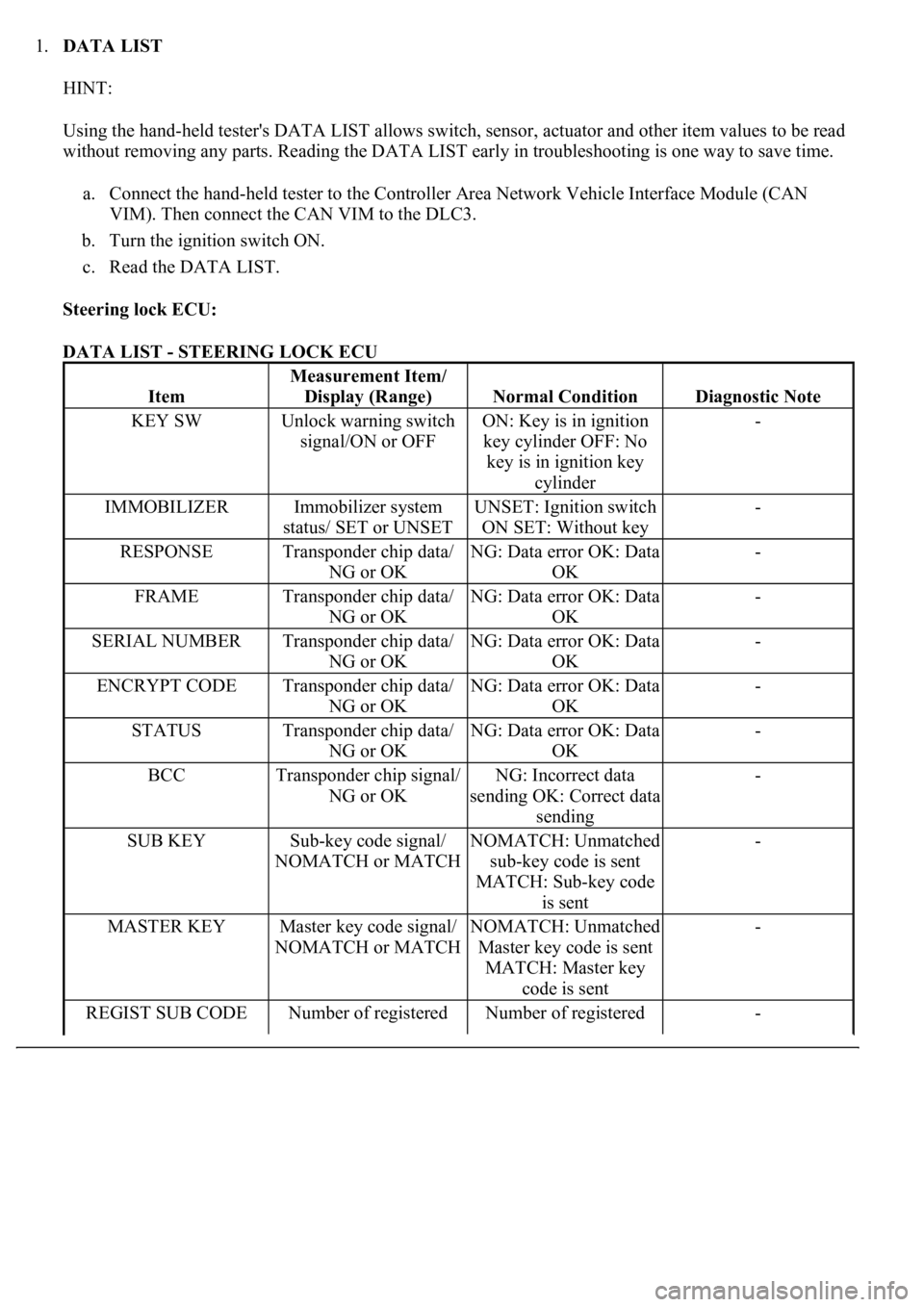
1.DATA LIST
HINT:
Using the hand-held tester's DATA LIST allows switch, sensor, actuator and other item values to be read
without removing any parts. Reading the DATA LIST early in troubleshooting is one way to save time.
a. Connect the hand-held tester to the Controller Area Network Vehicle Interface Module (CAN
VIM). Then connect the CAN VIM to the DLC3.
b. Turn the ignition switch ON.
c. Read the DATA LIST.
Steering lock ECU:
DATA LIST - STEERING LOCK ECU
Item
Measurement Item/
Display (Range)
Normal ConditionDiagnostic Note
KEY SWUnlock warning switch
signal/ON or OFFON: Key is in ignition
key cylinder OFF: No
key is in ignition key
cylinder-
IMMOBILIZERImmobilizer system
status/ SET or UNSETUNSET: Ignition switch
ON SET: Without key-
RESPONSETransponder chip data/
NG or OKNG: Data error OK: Data
OK-
FRAMETransponder chip data/
NG or OKNG: Data error OK: Data
OK-
SERIAL NUMBERTransponder chip data/
NG or OKNG: Data error OK: Data
OK-
ENCRYPT CODETransponder chip data/
NG or OKNG: Data error OK: Data
OK-
STATUSTransponder chip data/
NG or OKNG: Data error OK: Data
OK-
BCCTransponder chip signal/
NG or OKNG: Incorrect data
sending OK: Correct data
sending-
SUB KEYSub-key code signal/
NOMATCH or MATCHNOMATCH: Unmatched
sub-key code is sent
MATCH: Sub-key code
is sent-
MASTER KEYMaster key code signal/
NOMATCH or MATCHNOMATCH: Unmatched
Master key code is sent
MATCH: Master key
code is sent-
REGIST SUB CODENumber of registered Number of registered -
Page 3199 of 4500
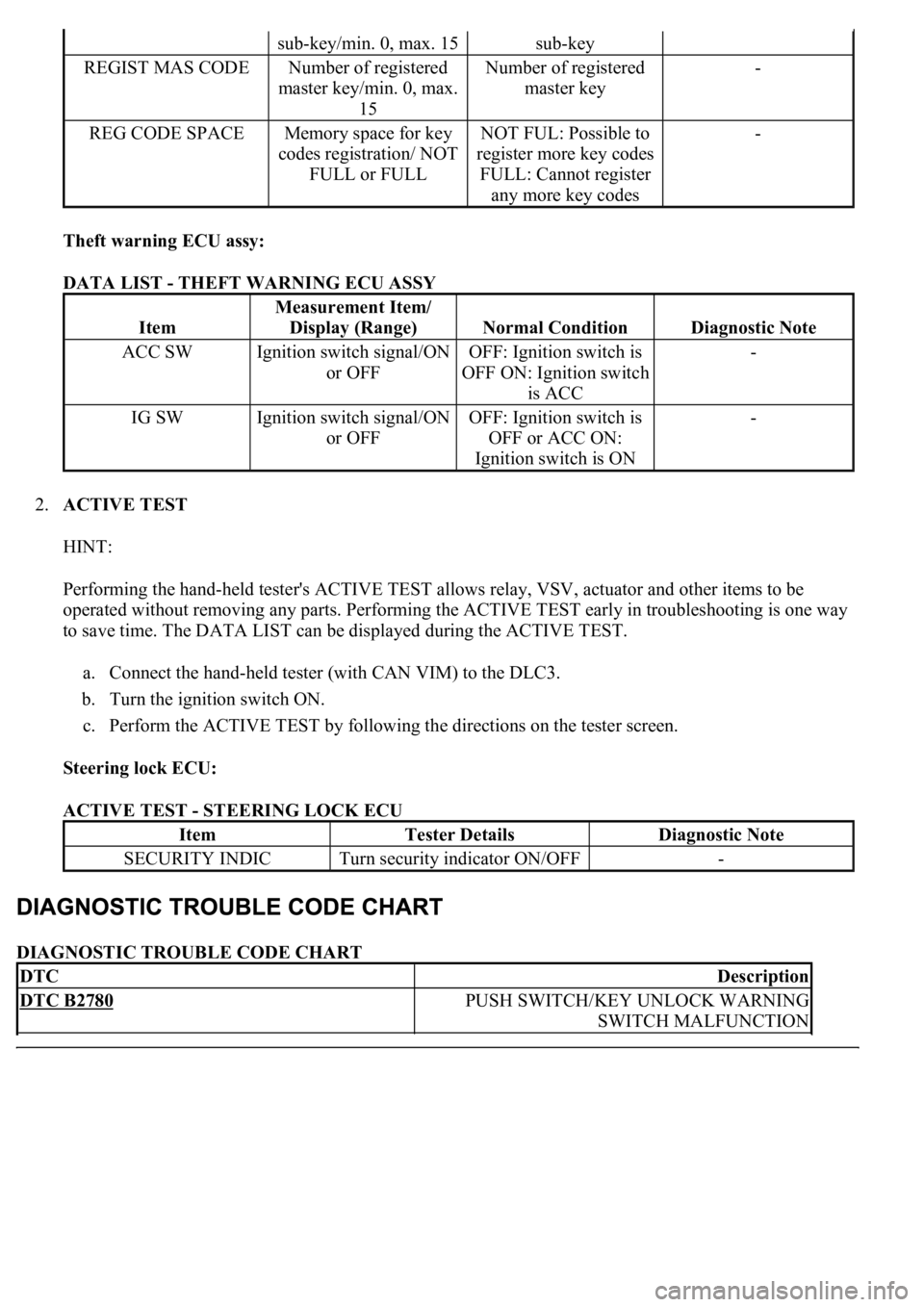
Theft warning ECU assy:
DATA LIST - THEFT WARNING ECU ASSY
2.ACTIVE TEST
HINT:
Performing the hand-held tester's ACTIVE TEST allows relay, VSV, actuator and other items to be
operated without removing any parts. Performing the ACTIVE TEST early in troubleshooting is one way
to save time. The DATA LIST can be displayed during the ACTIVE TEST.
a. Connect the hand-held tester (with CAN VIM) to the DLC3.
b. Turn the ignition switch ON.
c. Perform the ACTIVE TEST by following the directions on the tester screen.
Steering lock ECU:
ACTIVE TEST - STEERING LOCK ECU
DIAGNOSTIC TROUBLE CODE CHART
sub-key/min. 0, max. 15sub-key
REGIST MAS CODENumber of registered
master key/min. 0, max.
15Number of registered
master key-
REG CODE SPACEMemory space for key
codes registration/ NOT
FULL or FULLNOT FUL: Possible to
register more key codes
FULL: Cannot register
any more key codes-
Item
Measurement Item/
Display (Range)
Normal ConditionDiagnostic Note
ACC SWIgnition switch signal/ON
or OFFOFF: Ignition switch is
OFF ON: Ignition switch
is ACC-
IG SWIgnition switch signal/ON
or OFFOFF: Ignition switch is
OFF or ACC ON:
Ignition switch is ON-
ItemTester DetailsDiagnostic Note
SECURITY INDICTurn security indicator ON/OFF-
DTCDescription
DTC B2780PUSH SWITCH/KEY UNLOCK WARNING
SWITCH MALFUNCTION
Page 3227 of 4500
receives the faint electric wave. Upon receiving the faint electric wave, the transponder chip outputs a key
ID code signal. The transponder key coil receives this signal, the transponder key amplifier amplifies it,
and then the signal is transmitted to the ECU.
The ECU matches the key's ID code with the vehicle's ID code, which was previously registered in the
ECU, and then communicates the results to the ECM using SFI communication.
After the identification results show that the key's ID code matches the vehicle's ID code and the ECU has
confirmed their match: 1) the immobilizer system does not immobilize the engine and the engine starting
controls (fuel injection control and ignition control) enter standby mode; and 2) the ECU transmits a
security indicator signal that communicates "indicator off" to the theft warning ECU (theft deterrent
ECU). Then, the theft warning ECU turns off the security indicator lamp.
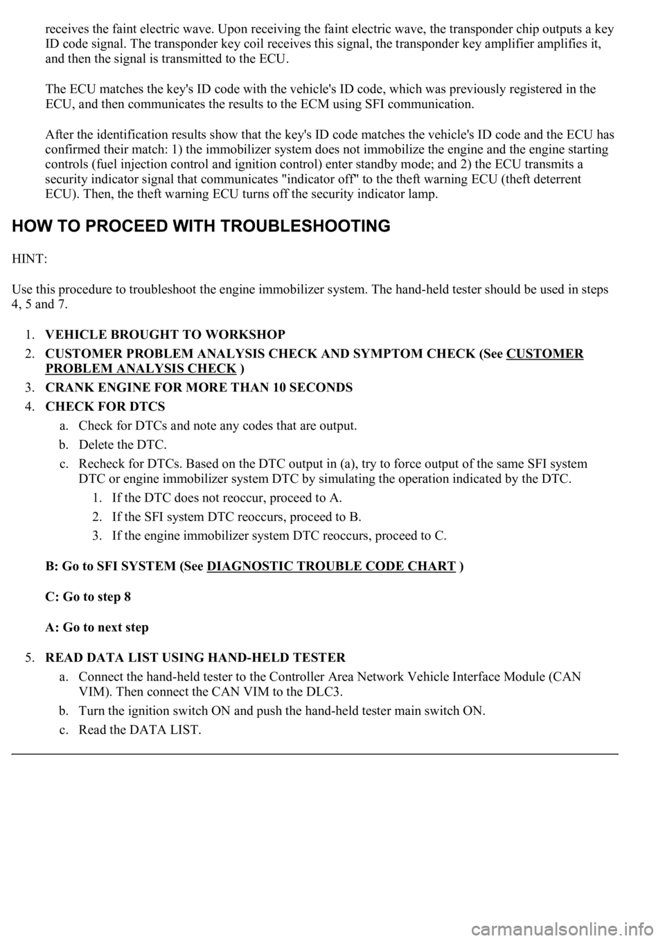
HINT:
<00380056004800030057004b004c00560003005300550052004600480047005800550048000300570052000300570055005200580045004f00480056004b00520052005700030057004b0048000300480051004a004c005100480003004c00500050005200
45004c004f004c005d0048005500030056005c005600570048[m. The hand-held tester should be used in steps
4, 5 and 7.
1.VEHICLE BROUGHT TO WORKSHOP
2.CUSTOMER PROBLEM ANALYSIS CHECK AND SYMPTOM CHECK (See CUSTOMER
PROBLEM ANALYSIS CHECK )
3.CRANK ENGINE FOR MORE THAN 10 SECONDS
4.CHECK FOR DTCS
a. Check for DTCs and note any codes that are output.
b. Delete the DTC.
c. Recheck for DTCs. Based on the DTC output in (a), try to force output of the same SFI system
DTC or engine immobilizer system DTC by simulating the operation indicated by the DTC.
1. If the DTC does not reoccur, proceed to A.
2. If the SFI system DTC reoccurs, proceed to B.
3. If the engine immobilizer system DTC reoccurs, proceed to C.
B: Go to SFI SYSTEM (See DIAGNOSTIC TROUBLE CODE CHART
)
C: Go to step 8
A: Go to next step
5.READ DATA LIST USING HAND-HELD TESTER
a. Connect the hand-held tester to the Controller Area Network Vehicle Interface Module (CAN
VIM). Then connect the CAN VIM to the DLC3.
b. Turn the ignition switch ON and push the hand-held tester main switch ON.
c. Read the DATA LIST.
Page 3250 of 4500
The vehicle uses the ISO 15765-4 communication protocol. The terminal arrangement of the DLC3
complies with SAE J1962 and matches the ISO 15765-4 format.
Fig. 21: Identifying DLC3 Connector Terminals
Courtesy of TOYOTA MOTOR SALES, U.S.A., INC.
DLC3 - REFERENCE TABLE
If the result is not as specified, the DLC3 may have a malfunction. Repair or replace the harness and
connector.
HINT:
Connect the cable of the han
d-held tester (with CAN VIM) to the DLC3, turn the ignition switch ON and
Symbols (Terminals No.)Terminal DescriptionConditionSpecified condition
SIL (7) - SG (5)Bus "+" lineDuring transmissionPulse generation
CG (4) - Body groundChassis groundAlwaysBelow 1 ohms
SG (5) - Body groundSignal groundAlwaysBelow 1 ohms
BAT (16) - Body groundBattery positiveAlways11 to 14V
Page 3253 of 4500
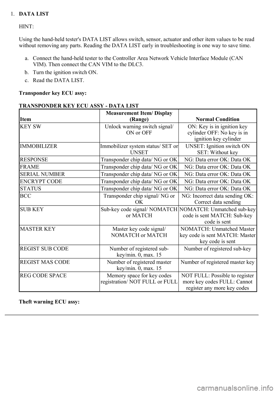
1.DATA LIST
HINT:
Using the hand-held tester's DATA LIST allows switch, sensor, actuator and other item values to be read
without removing any parts. Reading the DATA LIST early in troubleshooting is one way to save time.
a. Connect the hand-held tester to the Controller Area Network Vehicle Interface Module (CAN
VIM). Then connect the CAN VIM to the DLC3.
b. Turn the ignition switch ON.
c. Read the DATA LIST.
Transponder key ECU assy:
TRANSPONDER KEY ECU ASSY - DATA LIST
Theft warning ECU assy:
Item
Measurement Item/ Display
(Range)
Normal Condition
KEY SWUnlock warning switch signal/
ON or OFFON: Key is in ignition key
cylinder OFF: No key is in
ignition key cylinder
IMMOBILIZERImmobilizer system status/ SET or
UNSETUNSET: Ignition switch ON
SET: Without key
RESPONSETransponder chip data/ NG or OKNG: Data error OK: Data OK
FRAMETransponder chip data/ NG or OKNG: Data error OK: Data OK
SERIAL NUMBERTransponder chip data/ NG or OKNG: Data error OK: Data OK
ENCRYPT CODETransponder chip data/ NG or OKNG: Data error OK: Data OK
STATUSTransponder chip data/ NG or OKNG: Data error OK: Data OK
BCCTransponder chip signal/ NG or
OKNG: Incorrect data sending OK:
Correct data sending
SUB KEYSub-key code signal/ NOMATCH
or MATCHNOMATCH: Unmatched sub-key
code is sent MATCH: Sub-key
code is sent
MASTER KEYMaster key code signal/
NOMATCH or MATCHNOMATCH: Unmatched Master
key code is sent MATCH: Master
key code is sent
REGIST SUB CODENumber of registered sub-
key/min. 0, max. 15Number of registered sub-key
REGIST MAS CODENumber of registered master
key/min. 0, max. 15Number of registered master key
REG CODE SPACEMemory space for key codes
registration/ NOT FULL or FULLNOT FULL: Possible to register
more key codes FULL: Cannot
register any more key codes
Page 3925 of 4500
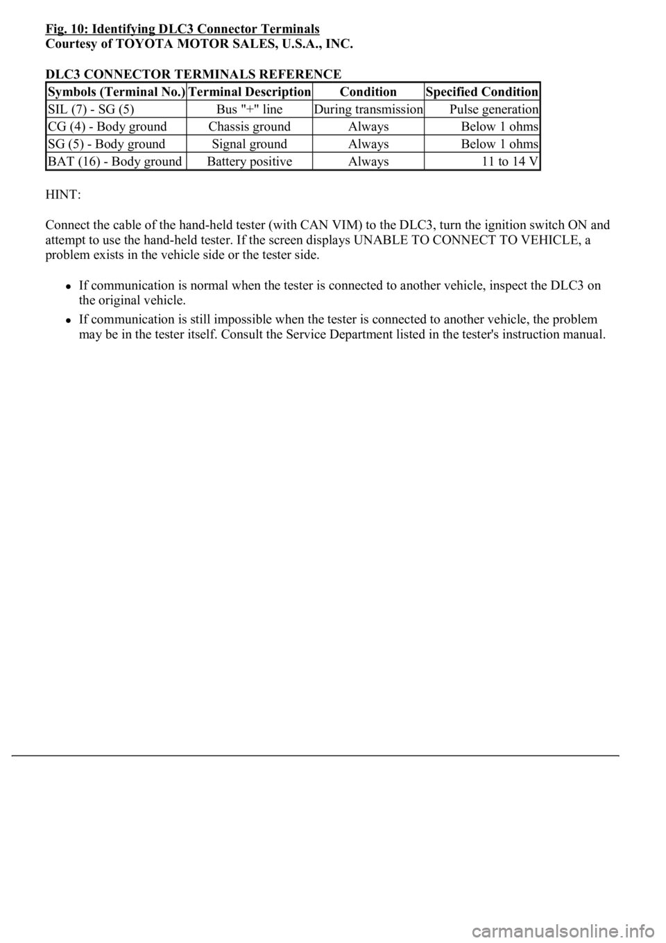
Fig. 10: Identifying DLC3 Connector Terminals
Courtesy of TOYOTA MOTOR SALES, U.S.A., INC.
DLC3 CONNECTOR TERMINALS REFERENCE
HINT:
Connect the cable of the hand-held tester (with CAN VIM) to the DLC3, turn the ignition switch ON and
attempt to use the hand-held tester. If the screen displays UNABLE TO CONNECT TO VEHICLE, a
problem exists in the vehicle side or the tester side.
If communication is normal when the tester is connected to another vehicle, inspect the DLC3 on
the original vehicle.
If communication is still impossible when the tester is connected to another vehicle, the problem
may be in the tester itself. Consult the Service Department listed in the tester's instruction manual.
Symbols (Terminal No.)Terminal DescriptionConditionSpecified Condition
SIL (7) - SG (5)Bus "+" lineDuring transmissionPulse generation
CG (4) - Body groundChassis groundAlwaysBelow 1 ohms
SG (5) - Body groundSignal groundAlwaysBelow 1 ohms
BAT (16) - Body groundBattery positiveAlways11 to 14 V
Page 3942 of 4500
Fig. 22: Identifying D27 Driver Seat ECU Connector Terminals And Power Seat Motor Connector
Terminals
Courtesy of TOYOTA MOTOR SALES, U.S.A., INC.
NG: REPAIR OR REPLACE WIRE HARNESS AND CONNECTOR
OK: PROCEED TO NEXT CIRCUIT INSPECTION SHOWN ON PROBLEM SYMPTOMS
TABLE
CIRCUIT DESCRIPTION
The position sensor detects seat movement and sends pulse signals to the driver seat ECU for use with the
memory function.
The ECU records the number of pulses relative to a previously recorded seat position and uses this data to
return the seat to that position.
If a malfunction occurs in a position sensor and seat movement does not result in pulse signals being input into
the ECU, the memory function is deactivated.
WIRING DIAGRAM