2003 LEXUS LS430 airbag
[x] Cancel search: airbagPage 2631 of 4500
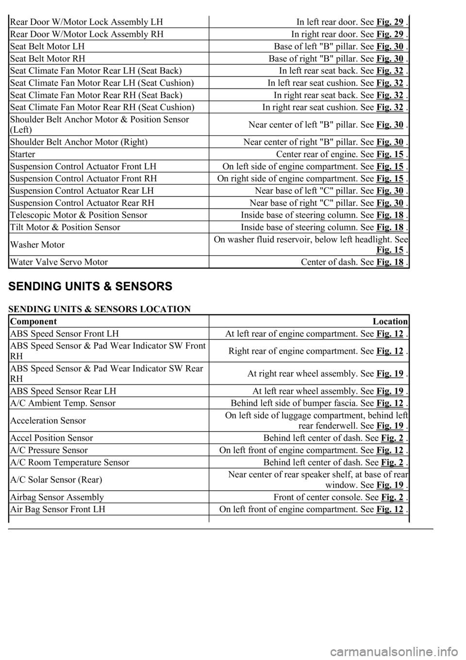
SENDING UNITS & SENSORS LOCATION
Rear Door W/Motor Lock Assembly LHIn left rear door. See Fig. 29 .
Rear Door W/Motor Lock Assembly RHIn right rear door. See Fig. 29 .
Seat Belt Motor LHBase of left "B" pillar. See Fig. 30 .
Seat Belt Motor RHBase of right "B" pillar. See Fig. 30 .
Seat Climate Fan Motor Rear LH (Seat Back)In left rear seat back. See Fig. 32 .
Seat Climate Fan Motor Rear LH (Seat Cushion)In left rear seat cushion. See Fig. 32 .
Seat Climate Fan Motor Rear RH (Seat Back)In right rear seat back. See Fig. 32 .
Seat Climate Fan Motor Rear RH (Seat Cushion)In right rear seat cushion. See Fig. 32 .
Shoulder Belt Anchor Motor & Position Sensor
(Left)Near center of left "B" pillar. See Fig. 30 .
Shoulder Belt Anchor Motor (Right)Near center of right "B" pillar. See Fig. 30 .
StarterCenter rear of engine. See Fig. 15 .
Suspension Control Actuator Front LHOn left side of engine compartment. See Fig. 15 .
Suspension Control Actuator Front RHOn right side of engine compartment. See Fig. 15 .
Suspension Control Actuator Rear LHNear base of left "C" pillar. See Fig. 30 .
Suspension Control Actuator Rear RHNear base of right "C" pillar. See Fig. 30 .
Telescopic Motor & Position SensorInside base of steering column. See Fig. 18 .
Tilt Motor & Position SensorInside base of steering column. See Fig. 18 .
Washer MotorOn washer fluid reservoir, below left headlight. See
Fig. 15
.
Water Valve Servo MotorCenter of dash. See Fig. 18 .
ComponentLocation
ABS Speed Sensor Front LHAt left rear of engine compartment. See Fig. 12 .
ABS Speed Sensor & Pad Wear Indicator SW Front
RHRight rear of engine compartment. See Fig. 12 .
ABS Speed Sensor & Pad Wear Indicator SW Rear
RHAt right rear wheel assembly. See Fig. 19 .
ABS Speed Sensor Rear LHAt left rear wheel assembly. See Fig. 19 .
A/C Ambient Temp. SensorBehind left side of bumper fascia. See Fig. 12 .
Acceleration SensorOn left side of luggage compartment, behind left
rear fenderwell. See Fig. 19
.
Accel Position SensorBehind left center of dash. See Fig. 2 .
A/C Pressure SensorOn left front of engine compartment. See Fig. 12 .
A/C Room Temperature SensorBehind left center of dash. See Fig. 2 .
A/C Solar Sensor (Rear)Near center of rear speaker shelf, at base of rear
window. See Fig. 19
.
Airbag Sensor AssemblyFront of center console. See Fig. 2 .
Air Bag Sensor Front LHOn left front of engine compartment. See Fig. 12 .
Page 2635 of 4500
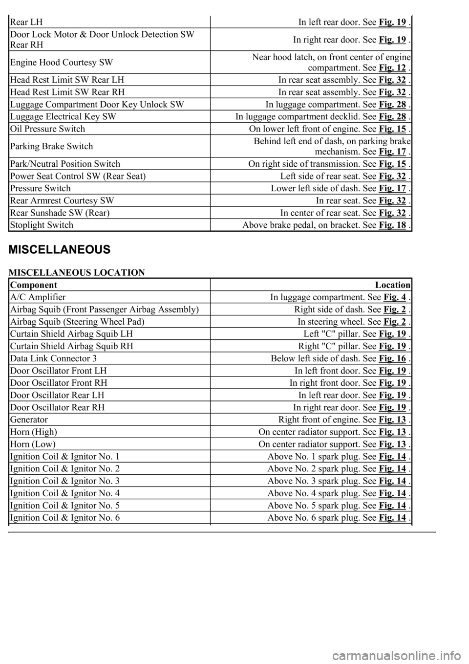
MISCELLANEOUS LOCATION
Rear LHIn left rear door. See Fig. 19 .
Door Lock Motor & Door Unlock Detection SW
Rear RHIn right rear door. See Fig. 19 .
Engine Hood Courtesy SWNear hood latch, on front center of engine
compartment. See Fig. 12
.
Head Rest Limit SW Rear LHIn rear seat assembly. See Fig. 32 .
Head Rest Limit SW Rear RHIn rear seat assembly. See Fig. 32 .
Luggage Compartment Door Key Unlock SWIn luggage compartment. See Fig. 28 .
Luggage Electrical Key SWIn luggage compartment decklid. See Fig. 28 .
Oil Pressure SwitchOn lower left front of engine. See Fig. 15 .
Parking Brake SwitchBehind left end of dash, on parking brake
mechanism. See Fig. 17
.
Park/Neutral Position SwitchOn right side of transmission. See Fig. 15 .
Power Seat Control SW (Rear Seat)Left side of rear seat. See Fig. 32 .
Pressure SwitchLower left side of dash. See Fig. 17 .
Rear Armrest Courtesy SWIn rear seat. See Fig. 32 .
Rear Sunshade SW (Rear)In center of rear seat. See Fig. 32 .
Stoplight SwitchAbove brake pedal, on bracket. See Fig. 18 .
ComponentLocation
A/C AmplifierIn luggage compartment. See Fig. 4 .
Airbag Squib (Front Passenger Airbag Assembly)Right side of dash. See Fig. 2 .
Airbag Squib (Steering Wheel Pad)In steering wheel. See Fig. 2 .
Curtain Shield Airbag Squib LHLeft "C" pillar. See Fig. 19 .
Curtain Shield Airbag Squib RHRight "C" pillar. See Fig. 19 .
Data Link Connector 3Below left side of dash. See Fig. 16 .
Door Oscillator Front LHIn left front door. See Fig. 19 .
Door Oscillator Front RHIn right front door. See Fig. 19 .
Door Oscillator Rear LHIn left rear door. See Fig. 19 .
Door Oscillator Rear RHIn right rear door. See Fig. 19 .
GeneratorRight front of engine. See Fig. 13 .
Horn (High)On center radiator support. See Fig. 13 .
Horn (Low)On center radiator support. See Fig. 13 .
Ignition Coil & Ignitor No. 1Above No. 1 spark plug. See Fig. 14 .
Ignition Coil & Ignitor No. 2Above No. 2 spark plug. See Fig. 14 .
Ignition Coil & Ignitor No. 3Above No. 3 spark plug. See Fig. 14 .
Ignition Coil & Ignitor No. 4Above No. 4 spark plug. See Fig. 14 .
Ignition Coil & Ignitor No. 5Above No. 5 spark plug. See Fig. 14 .
Ignition Coil & Ignitor No. 6Above No. 6 spark plug. See Fig. 14 .
Page 2636 of 4500
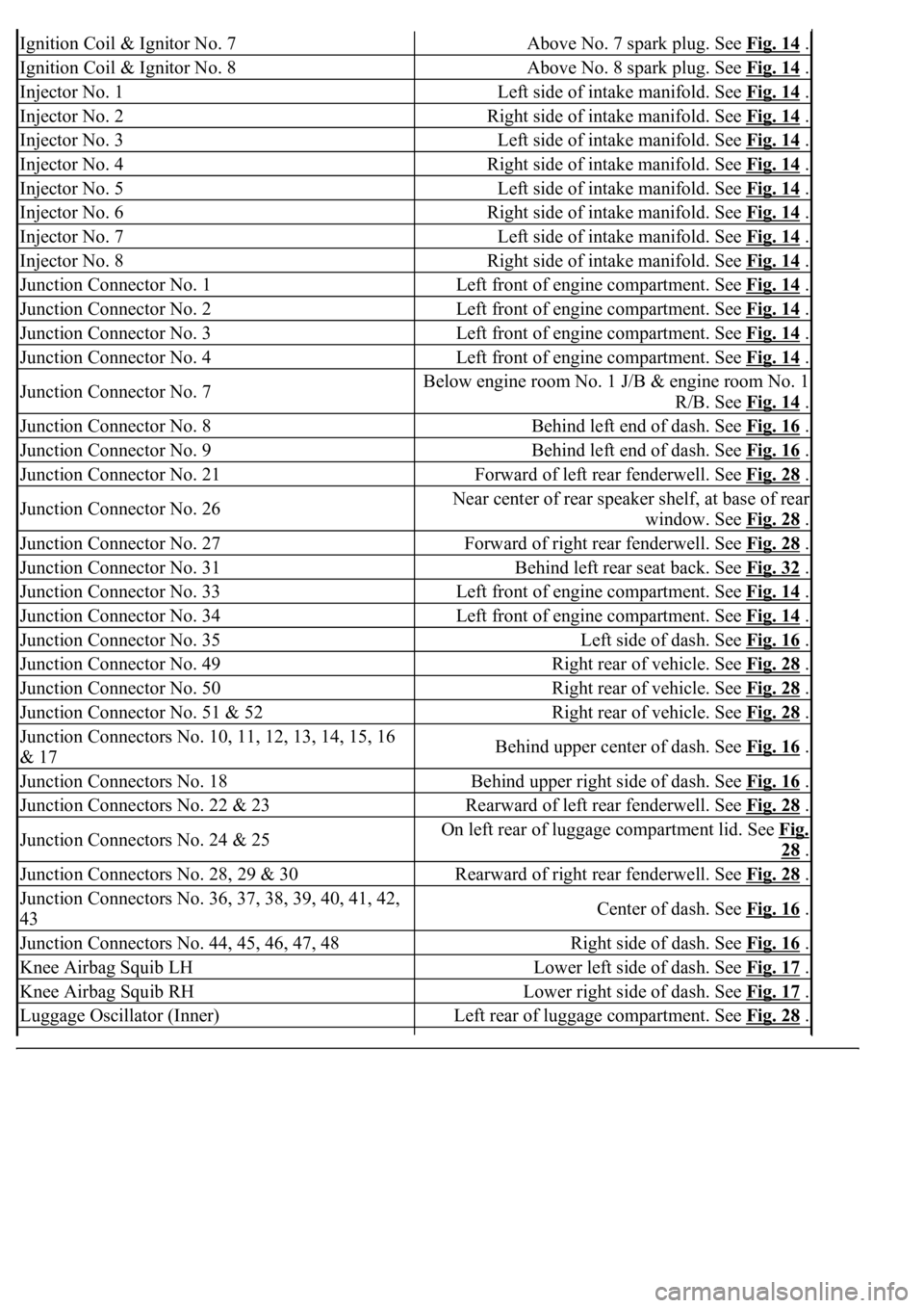
Ignition Coil & Ignitor No. 7Above No. 7 spark plug. See Fig. 14 .
Ignition Coil & Ignitor No. 8Above No. 8 spark plug. See Fig. 14 .
Injector No. 1Left side of intake manifold. See Fig. 14 .
Injector No. 2Right side of intake manifold. See Fig. 14 .
Injector No. 3Left side of intake manifold. See Fig. 14 .
Injector No. 4Right side of intake manifold. See Fig. 14 .
Injector No. 5Left side of intake manifold. See Fig. 14 .
Injector No. 6Right side of intake manifold. See Fig. 14 .
Injector No. 7Left side of intake manifold. See Fig. 14 .
Injector No. 8Right side of intake manifold. See Fig. 14 .
Junction Connector No. 1Left front of engine compartment. See Fig. 14 .
Junction Connector No. 2Left front of engine compartment. See Fig. 14 .
Junction Connector No. 3Left front of engine compartment. See Fig. 14 .
Junction Connector No. 4Left front of engine compartment. See Fig. 14 .
Junction Connector No. 7Below engine room No. 1 J/B & engine room No. 1
R/B. See Fig. 14
.
Junction Connector No. 8Behind left end of dash. See Fig. 16 .
Junction Connector No. 9Behind left end of dash. See Fig. 16 .
Junction Connector No. 21Forward of left rear fenderwell. See Fig. 28 .
Junction Connector No. 26Near center of rear speaker shelf, at base of rear
window. See Fig. 28
.
Junction Connector No. 27Forward of right rear fenderwell. See Fig. 28 .
Junction Connector No. 31Behind left rear seat back. See Fig. 32 .
Junction Connector No. 33Left front of engine compartment. See Fig. 14 .
Junction Connector No. 34Left front of engine compartment. See Fig. 14 .
Junction Connector No. 35Left side of dash. See Fig. 16 .
Junction Connector No. 49Right rear of vehicle. See Fig. 28 .
Junction Connector No. 50Right rear of vehicle. See Fig. 28 .
Junction Connector No. 51 & 52Right rear of vehicle. See Fig. 28 .
<002d0058005100460057004c00520051000300260052005100510048004600570052005500560003003100520011000300140013000f000300140014000f000300140015000f000300140016000f000300140017000f000300140018000f00030014001900
03[
& 17Behind upper center of dash. See Fig. 16 .
Junction Connectors No. 18Behind upper right side of dash. See Fig. 16 .
Junction Connectors No. 22 & 23Rearward of left rear fenderwell. See Fig. 28 .
Junction Connectors No. 24 & 25On left rear of luggage compartment lid. See Fig.
28 .
Junction Connectors No. 28, 29 & 30Rearward of right rear fenderwell. See Fig. 28 .
<002d0058005100460057004c00520051000300260052005100510048004600570052005500560003003100520011000300160019000f00030016001a000f00030016001b000f00030016001c000f000300170013000f000300170014000f00030017001500
0f0003[
43Center of dash. See Fig. 16 .
Junction Connectors No. 44, 45, 46, 47, 48Right side of dash. See Fig. 16 .
Knee Airbag Squib LHLower left side of dash. See Fig. 17 .
Knee Airbag Squib RHLower right side of dash. See Fig. 17 .
Luggage Oscillator (Inner)Left rear of luggage compartment. See Fig. 28 .
Page 2637 of 4500
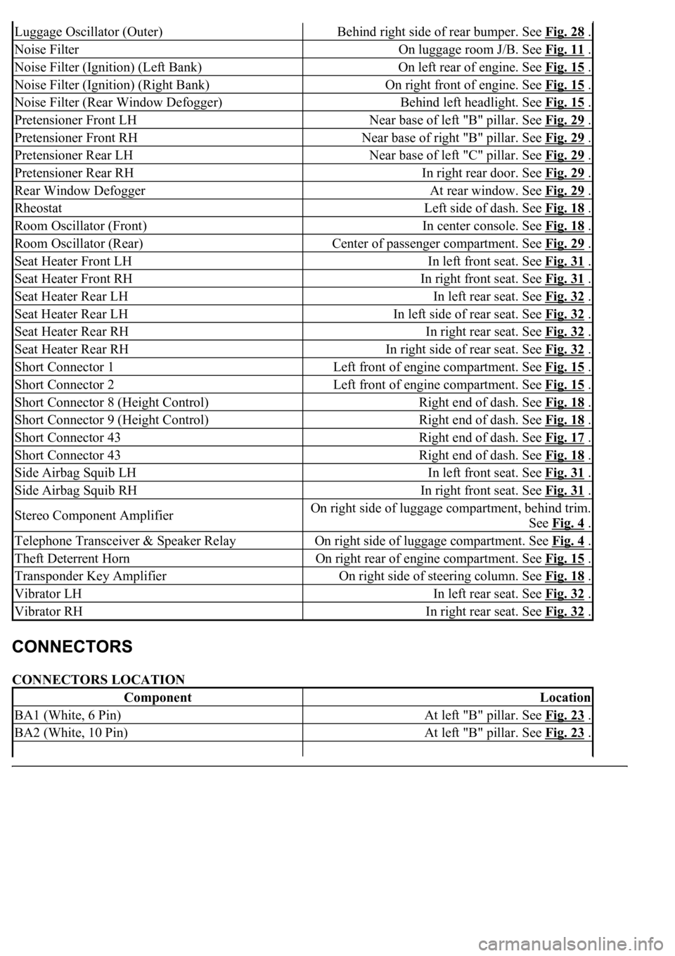
CONNECTORS LOCATION
Luggage Oscillator (Outer)Behind right side of rear bumper. See Fig. 28 .
Noise FilterOn luggage room J/B. See Fig. 11 .
Noise Filter (Ignition) (Left Bank)On left rear of engine. See Fig. 15 .
Noise Filter (Ignition) (Right Bank)On right front of engine. See Fig. 15 .
Noise Filter (Rear Window Defogger)Behind left headlight. See Fig. 15 .
Pretensioner Front LHNear base of left "B" pillar. See Fig. 29 .
Pretensioner Front RHNear base of right "B" pillar. See Fig. 29 .
Pretensioner Rear LHNear base of left "C" pillar. See Fig. 29 .
Pretensioner Rear RHIn right rear door. See Fig. 29 .
Rear Window DefoggerAt rear window. See Fig. 29 .
RheostatLeft side of dash. See Fig. 18 .
Room Oscillator (Front)In center console. See Fig. 18 .
Room Oscillator (Rear)Center of passenger compartment. See Fig. 29 .
Seat Heater Front LHIn left front seat. See Fig. 31 .
Seat Heater Front RHIn right front seat. See Fig. 31 .
Seat Heater Rear LHIn left rear seat. See Fig. 32 .
Seat Heater Rear LHIn left side of rear seat. See Fig. 32 .
Seat Heater Rear RHIn right rear seat. See Fig. 32 .
Seat Heater Rear RHIn right side of rear seat. See Fig. 32 .
Short Connector 1Left front of engine compartment. See Fig. 15 .
Short Connector 2Left front of engine compartment. See Fig. 15 .
Short Connector 8 (Height Control)Right end of dash. See Fig. 18 .
Short Connector 9 (Height Control)Right end of dash. See Fig. 18 .
Short Connector 43Right end of dash. See Fig. 17 .
Short Connector 43Right end of dash. See Fig. 18 .
Side Airbag Squib LHIn left front seat. See Fig. 31 .
Side Airbag Squib RHIn right front seat. See Fig. 31 .
Stereo Component AmplifierOn right side of luggage compartment, behind trim.
See Fig. 4
.
Telephone Transceiver & Speaker RelayOn right side of luggage compartment. See Fig. 4 .
Theft Deterrent HornOn right rear of engine compartment. See Fig. 15 .
Transponder Key AmplifierOn right side of steering column. See Fig. 18 .
Vibrator LHIn left rear seat. See Fig. 32 .
Vibrator RHIn right rear seat. See Fig. 32 .
ComponentLocation
BA1 (White, 6 Pin)At left "B" pillar. See Fig. 23 .
BA2 (White, 10 Pin)At left "B" pillar. See Fig. 23 .
Page 3016 of 4500
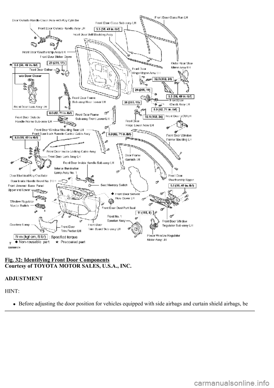
Fig. 32: Identifying Front Door Components
Courtesy of TOYOTA MOTOR SALES, U.S.A., INC.
ADJUSTMENT
HINT:
Before adjusting<00030057004b0048000300470052005200550003005300520056004c0057004c005200510003004900520055000300590048004b004c0046004f004800560003004800540058004c00530053004800470003005a004c0057004b00030056004c0047004800
030044004c005500450044[gs and curtain shield airbags, be
Page 3017 of 4500
sure to disconnect the battery. After adjustment, inspect the SRS warning lamp, the side airbag system
and the curtain shield airbag system for normal operation (see DIAGNOSIS SYSTEM
). Then initialize
both airbag systems (see INITIALIZATION
).
<00380056004800030057004b0048000300560044005000480003005300550052004600480047005800550048000300490052005500030057004b004800030035002b00030056004c0047004800030044005100470003002f002b00030056004c0047004800
1100030003[
The procedures listed below are for the LH side.
Centering bolts are used to mount the door hinge to the vehicle body and door. The door cannot be
adjusted with the centering bolts on. Substitute the centering bolts with standard bolts (w/washers) when
making adjustments.
A bolt without a torque specification is shown in the standard bolt chart (see STANDARD BOLT ).
Fig. 33: Identifying Centering Bolts
Courtesy of TOYOTA MOTOR SALES, U.S.A., INC.
1.INSPECT FRONT DOOR PANEL SUB-ASSY LH
a. Check that the clearance is within the standard ran
ge.
Page 3072 of 4500
Before adjusting the door position for vehicles equipped with side airbags and curtain shield airbags, be
sure to disconnect the battery. After adjustment, inspect the SRS warning lamp, the side airbag system
and the curtain shield airbag system for normal operation (see DIAGNOSIS SYSTEM
). Then initialize
both systems (see INITIALIZATION
).
<00380056004800030057004b0048000300560044005000480003005300550052004600480047005800550048000300490052005500030057004b004800030035002b00030056004c0047004800030044005100470003002f002b00030056004c0047004800
1100030003[
The procedures listed below are for the LH side.
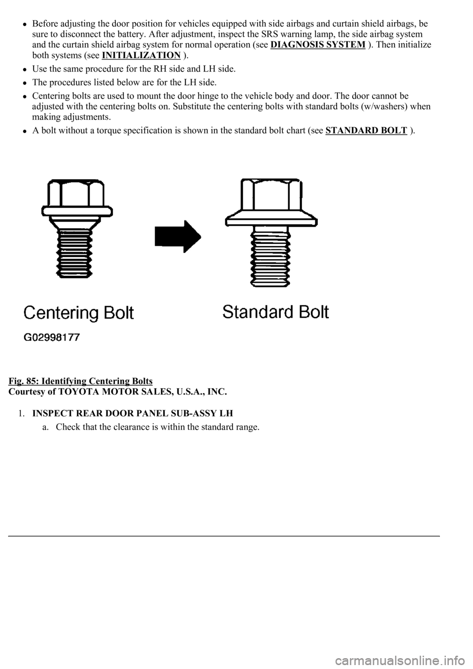
Centering bolts are used to mount the door hinge to the vehicle body and door. The door cannot be
adjusted with the centering bolts on. Substitute the centering bolts with standard bolts (w/washers) when
making adjustments.
A bolt without a torque specification is shown in the standard bolt chart (see STANDARD BOLT ).
Fig. 85: Identifying Centering Bolts
Courtesy of TOYOTA MOTOR SALES, U.S.A., INC.
1.INSPECT REAR DOOR PANEL SUB-ASSY LH
a. Check that the clearance is within the standard ran
ge.
Page 4258 of 4500
Installation is in the reverse order of removal.
See COMPONENTS .
1.DISCONNECT NEGATIVE TERMINAL CABLE FROM BATTERY
2.REMOVE FRONT DOOR SCUFF PLATE LH (See REPLACEMENT
)
3.REMOVE FRONT PILLAR GARNISH LH (See step 33 in REPLACEMENT
)
4.REMOVE INSTRUMENT PANEL UNDER COVER SUB-ASSY NO. 2 (See step 21 in
REPLACEMENT
)
5.REMOVE INSTRUMENT PANEL GARNISH SUB-ASSY RH (See step 22 in REPLACEMENT
)
6.REMOVE GLOVE COMPARTMENT DOOR ASSY W/ INSTRUMENT PANEL AIRBAG ASSY
LOWER NO. 2 (See step 25 in REPLACEMENT
)
7.REMOVE AIR SUSPENSION AND HEADLIGHT BEAM LEVEL CONTROL ECU
a. Disconnect the connectors.
b. Remove the 2 nuts and air suspension and headlight beam level control ECU.
8.REMOVE BLOWER ASSY
a. Disconnect the connectors.
b. Remove the nut and 3 bolts.
c. Remove the blower assy.