Page 1963 of 4500
15. Return the reflector to the original position and read the current angle.
DIVERGENCE OF BEAM AXIS TABLE
HINT:
When the values displayed on the screen are normal, the values are within the above range. If the
value is out of range, check the installation condition of the bumper reinforcement, etc.
16. Turn the headlamp dimmer switch to the TAIL position.
17. Press the "ENTER" key.
Fig. 16: Identifying "ENTER" Key
UPPER/LOWER SIDE-2° TO +2°
RIGHT/LEFT SIDE-4° TO +4°
Page 1965 of 4500
Fig. 18: Identifying "COMPLETE" Screen
Courtesy of TOYOTA MOTOR SALES, U.S.A., INC.
Page 1990 of 4500
Fig. 1: Identifying Defogger System Components And Replacements Location
Courtesy of TOYOTA MOTOR SALES, U.S.A., INC.
Page 1994 of 4500
Fig. 3: Identifying Customer Problem Analysis Check Sheet
Courtesy of TOYOTA MOTOR SALES, U.S.A., INC.
Fig. 4: Problem Symptoms Table
Courtesy of TOYOTA MOTOR SALES, U.S.A., INC.
1.CHECK A/C CONTROL ASSY (A/C ECU)
Fig. 5: Identifying A/C Control Assy Connector Terminals
Courtesy of TOYOTA MOTOR SALES, U.S.A., INC.
a. Disconnect the A11 ECU connector.
b. Measure the voltage and resistance of the wire harness side connector.
Standard:
A/C CONTROL ASSY - REFERENCE TABLE (DISCONNECTED)
Symbols Terminal Specified
Page 1996 of 4500

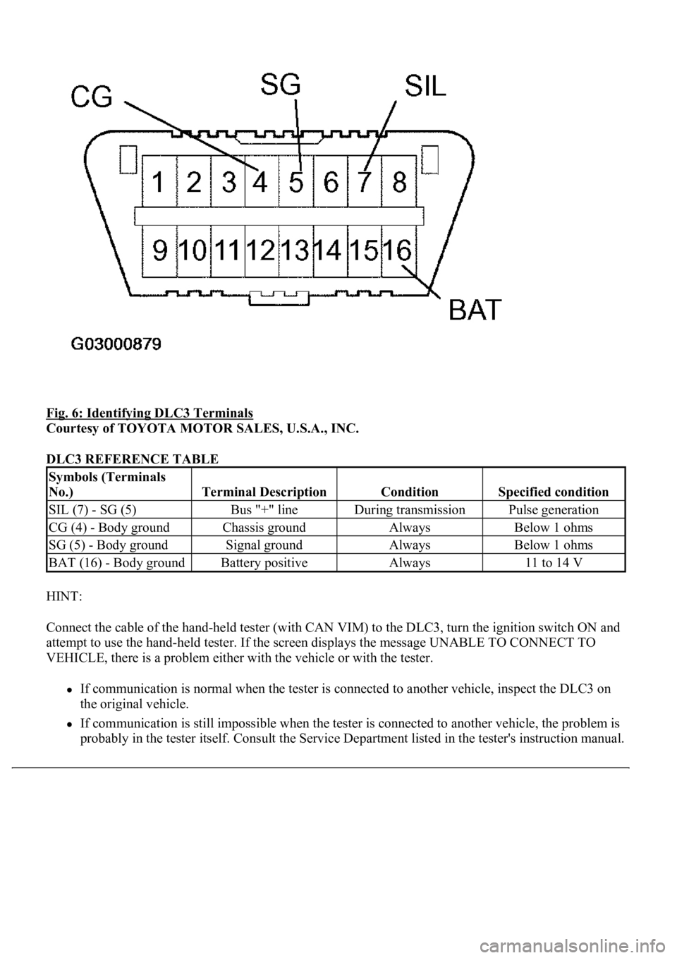
Fig. 6: Identifying DLC3 Terminals
Courtesy of TOYOTA MOTOR SALES, U.S.A., INC.
DLC3 REFERENCE TABLE
HINT:
Connect the cable of the hand-held tester (with CAN VIM) to the DLC3, turn the ignition switch ON and
attempt to use the hand-held tester. If the screen displays the message UNABLE TO CONNECT TO
VEHICLE, there is a problem either with the vehicle or with the tester.
If communication is normal when the tester is connected to another vehicle, inspect the DLC3 on
the original vehicle.
If communication is still impossible when the tester is connected to another vehicle, the problem is
probabl
y in the tester itself. Consult the Service Department listed in the tester's instruction manual.
Symbols (Terminals
No.)
Terminal DescriptionConditionSpecified condition
SIL (7) - SG (5)Bus "+" lineDuring transmissionPulse generation
CG (4) - Body groundChassis groundAlwaysBelow 1 ohms
SG (5) - Body groundSignal groundAlwaysBelow 1 ohms
BAT (16) - Body groundBattery positiveAlways11 to 14 V
Page 2040 of 4500
Fig. 2: Identifying Differential Components (1 Of 2)
Courtesy of TOYOTA MOTOR SALES, U.S.A., INC.
Page 2041 of 4500
Fig. 3: Identifying Differential Components (2 Of 2)
Courtesy of TOYOTA MOTOR SALES, U.S.A., INC.
ADJUSTMENT
1.INSPECT AND ADJUST DIFFERENTIAL OIL
Page 2084 of 4500
Fig. 44: Identifying Matchmarks On Ring Gear And Differential Case
Courtesy of TOYOTA MOTOR SALES, U.S.A., INC.
b. Remove the 10 ring gear set bolts.