Page 2191 of 4500
Fig. 13: Driver Door ECU Terminals Reference Chart
Courtesy of TOYOTA MOTOR SALES, U.S.A., INC.
If the result is not as specified, the driver door ECU may have a malfunction.
2.PASSENGER DOOR ECU
Fig. 14: Identifying Passenger Door ECU Terminals
Courtesy of TOYOTA MOTOR SALES, U.S.A., INC.
a. Disconnect the F17 and F24 ECU connectors.
b. Measure the voltage and resistance of the wire harness side connectors.
Page 2193 of 4500
Fig. 17: Identifying Rear Door ECU Terminals (LH)
Courtesy of TOYOTA MOTOR SALES, U.S.A., INC.
a. Disconnect the R13 and R36 ECU connectors.
b. Measure the voltage and resistance of the wire harness side connectors.
Fig. 18: Rear Door ECU Terminals Reference Chart (LH)
Courtesy of TOYOTA MOTOR SALES, U.S.A., INC.
If the result is not as specified, there may be a malfunction on the wire harness side.
c. Reconnect the R13 and R36 ECU connectors.
d. Measure the voltage of the connector.
Page 2194 of 4500
Fig. 19: Rear Door ECU Terminals Reference Chart (LH)
Courtesy of TOYOTA MOTOR SALES, U.S.A., INC.
If the result is not as specified, the ECU may have a malfunction.
4.REAR DOOR ECU RH
Fig. 20: Identifying Rear Door ECU Terminals (RH)
Courtesy of TOYOTA MOTOR SALES, U.S.A., INC.
a. Disconnect the R14 and R37 ECU connectors.
b. Measure the voltage and resistance of the wire harness side connectors.
Page 2196 of 4500

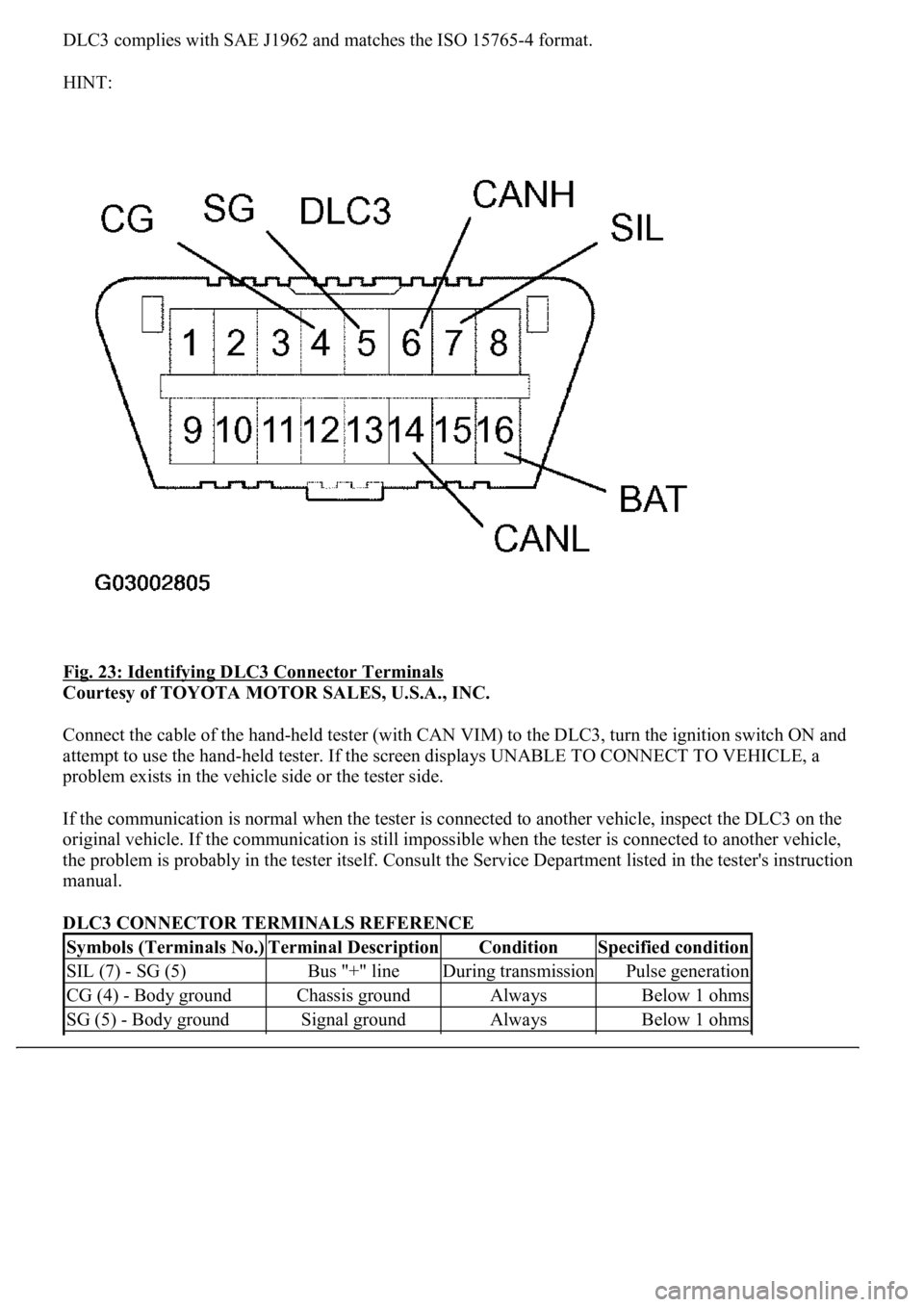
DLC3 complies with SAE J1962 and matches the ISO 15765-4 format.
HINT:
Fig. 23: Identifying DLC3 Connector Terminals
Courtesy of TOYOTA MOTOR SALES, U.S.A., INC.
Connect the cable of the hand-held tester (with CAN VIM) to the DLC3, turn the ignition switch ON and
attempt to use the hand-held tester. If the screen displays UNABLE TO CONNECT TO VEHICLE, a
problem exists in the vehicle side or the tester side.
If the communication is normal when the tester is connected to another vehicle, inspect the DLC3 on the
original vehicle. If the communication is still impossible when the tester is connected to another vehicle,
the problem is probably in the tester itself. Consult the Service Department listed in the tester's instruction
manual.
DLC3 CONNECTOR TERMINALS REFERENCE
Symbols (Terminals No.)Terminal DescriptionConditionSpecified condition
SIL (7) - SG (5)Bus "+" lineDuring transmissionPulse generation
CG (4) - Body groundChassis groundAlwaysBelow 1 ohms
SG (5) - Body groundSignal groundAlwaysBelow 1 ohms
Page 2310 of 4500
Fig. 6: Identifying Drive Shaft/Propeller Shaft Components (1 Of 5)
Courtesy of TOYOTA MOTOR SALES, U.S.A., INC.
Page 2311 of 4500
Fig. 7: Identifying Drive Shaft/Propeller Shaft Components (2 Of 5)
Courtesy of TOYOTA MOTOR SALES, U.S.A., INC.
Page 2312 of 4500
Fig. 8: Identifying Drive Shaft/Propeller Shaft Components (3 Of 5)
Courtesy of TOYOTA MOTOR SALES, U.S.A., INC.
Page 2313 of 4500
Fig. 9: Identifying Drive Shaft/Propeller Shaft Components (4 Of 5)
Courtesy of TOYOTA MOTOR SALES, U.S.A., INC.