Page 4445 of 4500

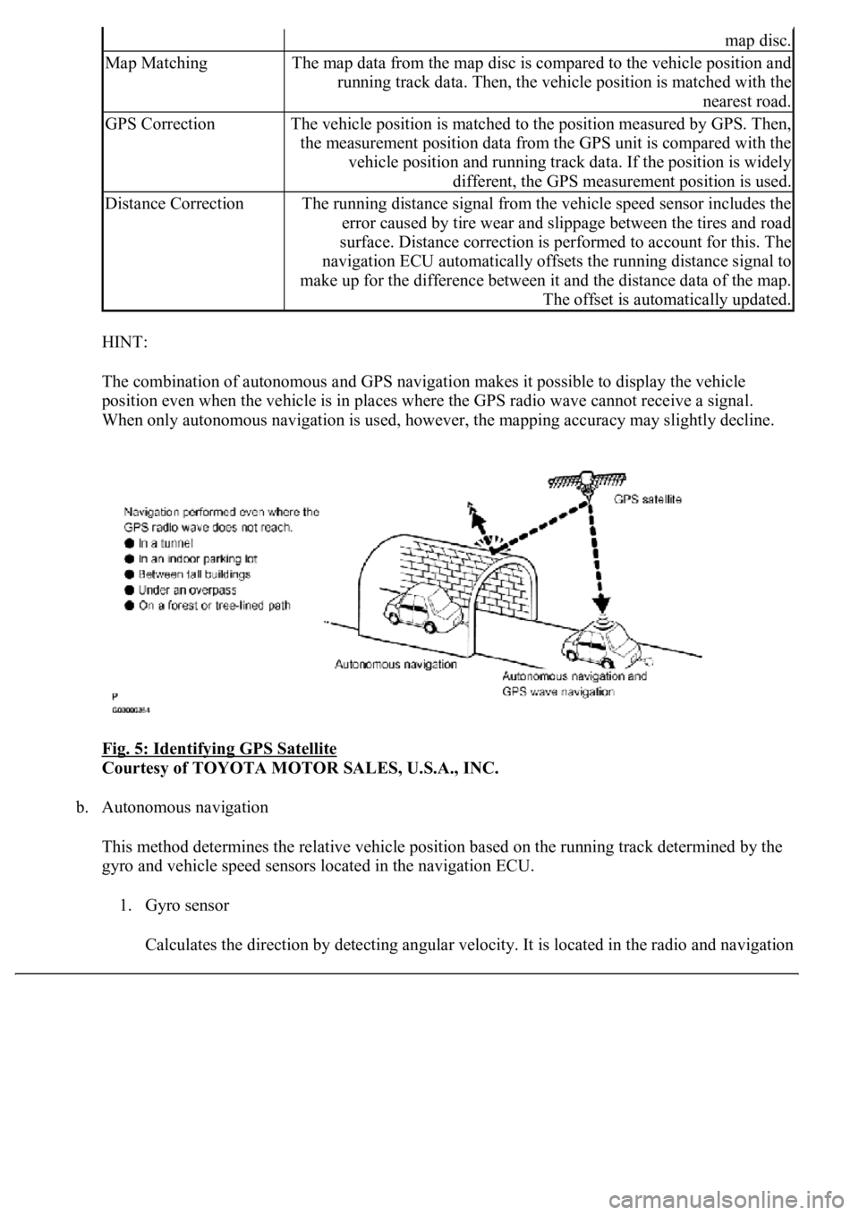
HINT:
The combination of autonomous and GPS navigation makes it possible to display the vehicle
position even when the vehicle is in places where the GPS radio wave cannot receive a signal.
<003a004b00480051000300520051004f005c000300440058005700520051005200500052005800560003005100440059004c004a00440057004c005200510003004c005600030058005600480047000f0003004b0052005a0048005900480055000f000300
57004b004800030050004400530053004c0051004a00030044[ccuracy may slightly decline.
Fig. 5: Identifying GPS Satellite
Courtesy of TOYOTA MOTOR SALES, U.S.A., INC.
b. Autonomous navigation
This method determines the relative vehicle position based on the running track determined by the
gyro and vehicle speed sensors located in the navigation ECU.
1. Gyro sensor
Calculates the direction b
y detecting angular velocity. It is located in the radio and navigation
map disc.
Map MatchingThe map data from the map disc is compared to the vehicle position and
running track data. Then, the vehicle position is matched with the
nearest road.
GPS CorrectionThe vehicle position is matched to the position measured by GPS. Then,
the measurement position data from the GPS unit is compared with the
vehicle position and running track data. If the position is widely
different, the GPS measurement position is used.
Distance CorrectionThe running distance signal from the vehicle speed sensor includes the
error caused by tire wear and slippage between the tires and road
surface. Distance correction is performed to account for this. The
navigation ECU automatically offsets the running distance signal to
make up for the difference between it and the distance data of the map.
The offset is automatically updated.
Page 4467 of 4500
Fig. 27: Identifying GPS Information Chart
Courtesy of TOYOTA MOTOR SALES, U.S.A., INC.
4.When GPS information is displayed, check the GPS conditions.
HINT:
This screen is updated once per second when input signals to the vehicle are changed.
HINT:
This mode checks the vehicle signal status to the navigation ECU.
Illustrations may differ from the actual vehicle depending on the device settings and options. Therefore,
some detailed areas may not be shown exactly the same as on the actual vehicle.
1.Enter diagnostic mode (see DIAGNOSTIC START
-UP/FINISH ).
Page 4486 of 4500
Fig. 47: Displaying Vehicle Signal Check Mode Screen
Courtesy of TOYOTA MOTOR SALES, U.S.A., INC.
Screen Description
NAME CONTENTS
HINT:
Only items sending a vehicle signal will be displayed.
This screen is updated once per second when input signals to the vehicle are changed.
3.NAVIGATION CHECK
a. Navigation Check MENU Screen
NameContents
BatteryBattery voltage is displayed.
PKBParking brake ON/OFF state is displayed.
REVReverse signal ON/OFF state is displayed.
IGIG switch ON/OFF state is displayed.
ADIM/TCANBrightness state DIM (with)/ BRIGHT (without) is displayed.
SPEEDThe vehicle speed, displayed in km/h.
TAILTAIL signal (Head lamp dimmer switch) ON/OFF state is displayed.