Page 1735 of 4500
REMOVAL AND INSTALLATION OF BATTERY TERMINAL
a. Before performing electronic work, disconnect the battery negative (-) terminal cable in order to prevent
it from shorting and burning out.
b. When disconnecting and reconnecting the battery cable, turn the ignition switch and lighting switch off
and loosen the terminal nut completely. Perform operations without twisting or prying on the terminal.
c. When the battery terminal cable is removed, the memories of the clock, radio, DTCs, etc. are erased. So
before removing it, check and make a note of them.
INITIALIZE SYSTEM REFERENCE
System NameSee Procedure
Front Power Seat Control SystemINITIALIZATION
Page 1744 of 4500

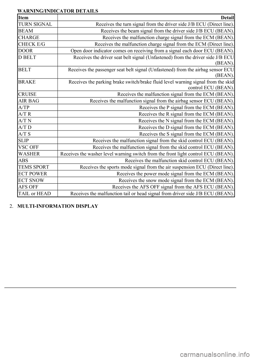
WARNING/INDICATOR DETAILS
2.MULTI-INFORMATION DISPLAY
ItemDetail
TURN SIGNALReceives the turn signal from the driver side J/B ECU (Direct line).
BEAMReceives the beam signal from the driver side J/B ECU (BEAN).
CHARGEReceives the malfunction charge signal from the ECM (BEAN).
CHECK E/GReceives the malfunction charge signal from the ECM (Direct line).
DOOROpen door indicator comes on receiving from a signal each door ECU (BEAN).
D BELTReceives the driver seat belt signal (Unfastened) from the driver side J/B ECU
(BEAN).
BELTReceives the passenger seat belt signal (Unfastened) from the airbag sensor ECU
(BEAN).
BRAKEReceives the parking brake switch/brake fluid level warning signal from the skid
control ECU (BEAN).
CRUISEReceives the malfunction signal from the ECM (BEAN).
AIR BAGReceives the malfunction signal from the airbag sensor ECU (BEAN).
A/TPReceives the P signal from the ECM (BEAN).
A/T RReceives the R signal from the ECM (BEAN).
A/T NReceives the N signal from the ECM (BEAN).
A/T DReceives the D signal from the ECM (BEAN).
A/T SReceives the S signal from the ECM (BEAN).
SLIPReceives the malfunction signal from the skid control ECU (BEAN).
VSC OFFReceives the malfunction signal from the skid control ECU (BEAN).
WASHERReceives the washer level warning switch from the front light control ECU (BEAN).
ABSReceives the malfunction skid control ECU (BEAN).
TEMS SPORTReceives the sports mode signal from the air suspension ECU (Direct line).
ECT POWERReceives the power mode signal from the ECM (BEAN).
ECT SNOWReceives the snow mode signal from the ECM (BEAN).
AFS OFFReceives the AFS OFF signal from the AFS ECU (BEAN).
TAIL or HEADReceives the malfunction tail or head signal from driver side J/B ECU (BEAN).
Page 1751 of 4500
MULTIPLEX DTC OUTPUTS (PROCEED TO "MULTIPLEX COMMUNICATION SYSTEM")
NO MULTIPLEX DTC (GO TO STEP 5)
5.CHECK CAN COMMUNICATION SYSTEM (SEE DIAGNOSTIC TROUBLE CODE CHART
)
a. Check for DTC outputs
CAN DTC OUTPUTS (PROCEED TO "CAN COMMUNICATION SYSTEM
")
NO CAN DTC (GO TO STEP 6)
6.CIRCUIT INSPECTION (SEE ENTIRE COMBINATION METER DOES NOT OPERATE
TO
OPERATING LIGHT CONTROL RHEOSTAT DOES NOT CHANGE LIGHT BRIGHTNESS
)
7.REPAIR OR REPLACE
8.CONFIRMATION TEST
END
Page 1756 of 4500

Once calibration is completed, it is not necessary to perform the above procedures unless the magnetic
field strength is drastically changed.
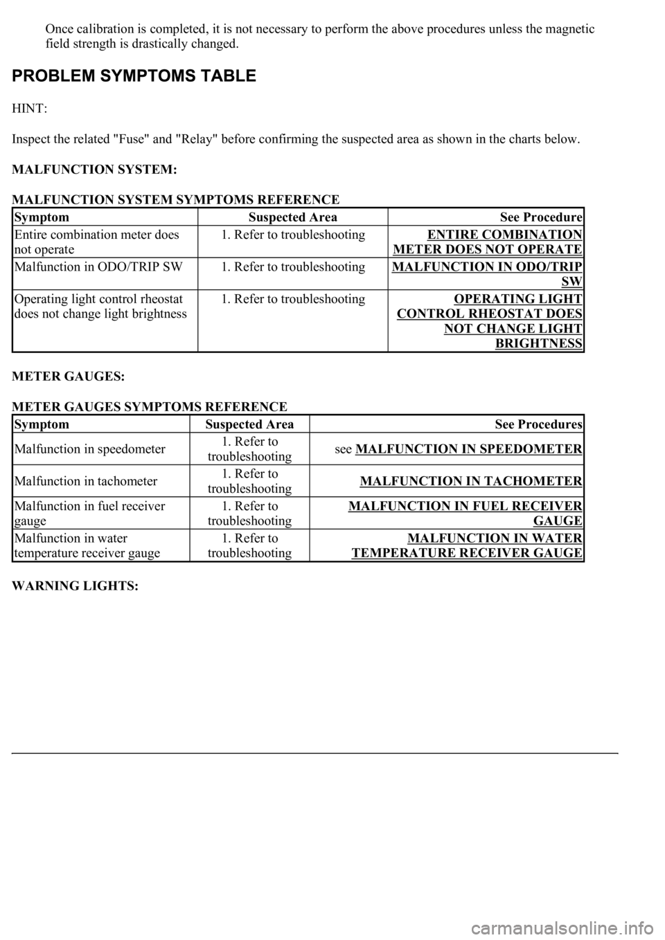
HINT:
Inspect the related "Fuse" and "Relay" before confirming the suspected area as shown in the charts below.
MALFUNCTION SYSTEM:
MALFUNCTION SYSTEM SYMPTOMS REFERENCE
METER GAUGES:
METER GAUGES SYMPTOMS REFERENCE
WARNING LIGHTS:
SymptomSuspected AreaSee Procedure
Entire combination meter does
not operate1. Refer to troubleshootingENTIRE COMBINATION
METER DOES NOT OPERATE
Malfunction in ODO/TRIP SW1. Refer to troubleshootingMALFUNCTION IN ODO/TRIP
SW
Operating light control rheostat
does not change light brightness1. Refer to troubleshootingOPERATING LIGHT
CONTROL RHEOSTAT DOES
NOT CHANGE LIGHT
BRIGHTNESS
SymptomSuspected AreaSee Procedures
Malfunction in speedometer1. Refer to
troubleshootingsee MALFUNCTION IN SPEEDOMETER
Malfunction in tachometer1. Refer to
troubleshootingMALFUNCTION IN TACHOMETER
Malfunction in fuel receiver
gauge1. Refer to
troubleshootingMALFUNCTION IN FUEL RECEIVER
GAUGE
Malfunction in water
temperature receiver gauge1. Refer to
troubleshootingMALFUNCTION IN WATER
TEMPERATURE RECEIVER GAUGE
Page 1757 of 4500
Fig. 20: Warning Lights Problem Symptoms Table
Courtesy of TOYOTA MOTOR SALES, U.S.A., INC.
INDICATOR LIGHTS:
Page 1758 of 4500
Fig. 21: Indicator Lights Problem Symptoms Table
Courtesy of TOYOTA MOTOR SALES, U.S.A., INC.
WARNING AREA:
Page 1762 of 4500
Fig. 26: Identifying Terminals Of ECU (Combination Meter Assy)
Courtesy of TOYOTA MOTOR SALES, U.S.A., INC.
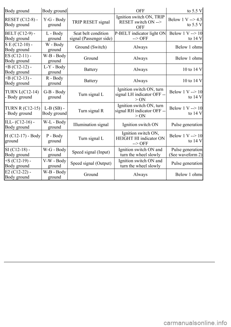
COMBINATION METER ASSY CONNECTOR TERMINALS REFERENCE
Symbols
(Terminals No.)Wiring
ColorTerminal DescriptionConditionSpecified
Condition
IG + (C12-1) -
Body groundY - Body
groundIgnition switch signal
(ON)Ignition switch OFF -->
ONBelow 1 V --> 10
to 14 V
MPX + (C12-2) -
Body groundGR-B -
Body groundMultiplex
communication signal--
MPX- (C12-3) -
Body groundGR-B -
Body groundMultiplex
communication signal--
S (C12-4) - Body
groundB-Y - Body
groundTachometer signalEngine runningPulse generation
(See waveform 1)
CHECK (C12-5) -
Body groundY-R - Body
groundCHECK ENGINE
signalCHECK ENGINE warning
light ON --> OFFBelow 1 V --> 10
to 14 V
TEMS (C12-6) -
Body groundY - Body
groundTEMS SPORT signalTEMS SPORT indicator
light ON --> OFFBelow 1 V --> 10
to 14 V
A/B (C12-7) - V-R (W) - ODO/TRIP signalIgnition switch ON,
ODO/TRIP switch ON -->
Below 1 V --> 4.5
Page 1763 of 4500

Body groundBody groundOFFto 5.5 V
RESET (C12-8) -
Body groundY-G - Body
groundTRIP RESET signal
Ignition switch ON, TRIP
RESET switch ON -->
OFFBelow 1 V --> 4.5
to 5.5 V
BELT (C12-9) -
Body groundL - Body
groundSeat belt condition
signal (Passenger side)P-BELT indicator light ON
--> OFFBelow 1 V --> 10
to 14 V
S E (C12-10) -
Body groundW - Body
groundGround (Switch)AlwaysBelow 1 ohms
ES (C12-11) -
Body groundW-B - Body
groundGroundAlwaysBelow 1 ohms
+B (C12-12) -
Body groundL-Y - Body
groundBatteryAlways10 to 14 V
+B (C12-13) -
Body groundR - Body
groundBatteryAlways10 to 14 V
TURN L(C12-14)
- Body groundG-B - Body
groundTurn signal L
Ignition switch ON, turn
signal LH indicator OFF --
> ONBelow 1 V --> 10
to 14 V
TURN R (C12-15)
- Body groundL-B (SB) -
Body groundTurn signal R
Ignition switch ON, turn
signal RH indicator OFF --
> ONBelow 1 V --> 10
to 14 V
ILL- (C12-16) -
Body groundW-L - Body
groundIllumination signalIgnition switch ONPulse generation
H (C12-17) - Body
groundP - Body
groundTurn signal L
Ignition switch ON,
HEIGHT HI indicator ON
--> OFFBelow 1 V --> 10
to 14 V
SI (C12-18) -
Body groundW-G - Body
groundSpeed signal (Input)Ignition switch ON and
turn the wheel slowlyPulse generation
(See waveform 2)
+S (C12-19) -
Body groundV-W - Body
groundSpeed signal (Output)Ignition switch ON and
turn the wheel slowlyPulse generation
E2 (C12-22) -
Body groundW-B - Body
groundGroundAlwaysBelow 1 ohms