Page 1018 of 4500
Using SST, adjust the booster push rod length until the push rod lightly touches the pin head.
SST 09737-00020
Fig. 51: Adjusting Booster Push Rod Length
Courtesy of TOYOTA MOTOR SALES, U.S.A., INC.
13.INSTALL BRAKE MASTER CYLINDER SUB-ASSY
a. Install the brake master cylinder sub-assy and vacuum check valve bracket with 2 nuts.
Torque: 13 N.m (130 kgf.cm, 9 ft.lbf)
b. Connect the brake fluid level warning switch connector to the master cylinder reservoir.
Page 1022 of 4500
pedal reserve distance.
b. Depress the brake pedal and start the engine. If the pedal goes down slightly, operation is normal.
If not, replace the brake booster.
Fig. 55: Identifying Brake Pedal Operation Check
Courtesy of TOYOTA MOTOR SALES, U.S.A., INC.
2.AIR TIGHTNESS CHECK
a. Start the engine and stop it after 1 or 2 minutes. Depress the brake pedal several times slowly.
If the pedal can be depressed to the floor the first time, but on the 2nd or 3rd time cannot be
depressed as far, the booster is airtight.
If not, replace the brake booster.
b. Depress the brake pedal while the engine is running, and stop the engine with the pedal depressed.
If there is no change in the pedal reserve travel after the pedal is held for 30 seconds, the booster is
air tight.
If not, replace the brake booster.
Page 1106 of 4500
Fig. 135: Installing Steering Sensor To Spiral Cable
Courtesy of TOYOTA MOTOR SALES, U.S.A., INC.
10.ADJUST CENTER FRONT WHEEL
11.INSTALL SPIRAL CABLE SUB-ASSY (SEE REPLACEMENT
)
12.CENTER SPIRAL CABLE (SEE REPLACEMENT
)
13.INSTALL STEERING COLUMN COVER
14.INSTALL STEERING WHEEL ASSY (SEE OVERHAUL
)
15.INSTALL HORN BUTTON ASSY (SEE OVERHAUL
)
16.INSPECT STEERING WHEEL CENTER POINT
17.INSPECT HORN BUTTON ASSY (SEE REPLACEMENT
)
18.INSPECT SRS WARNING LIGHT (SEE DIAGNOSIS SYSTEM
)
19.INSPECT ABS WARNING LIGHT AND VSC WARNING LIGHT (SEE DIAGNOSIS SYSTEM
)
PRECAUTION
Page 1108 of 4500

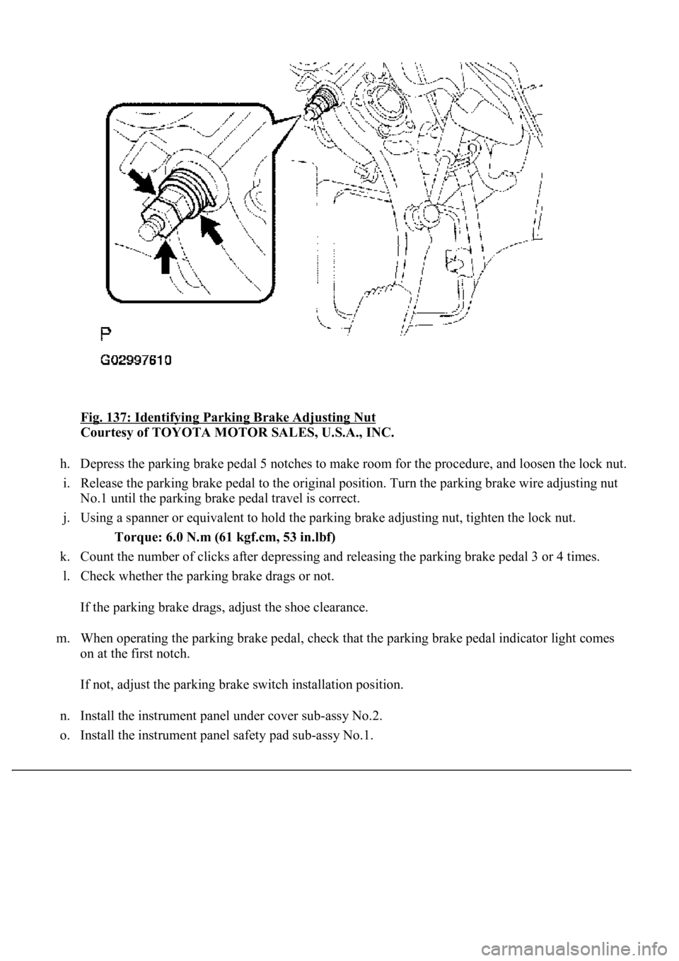
Fig. 137: Identifying Parking Brake Adjusting Nut
Courtesy of TOYOTA MOTOR SALES, U.S.A., INC.
h. Depress the parking brake pedal 5 notches to make room for the procedure, and loosen the lock nut.
i. Release the parking brake pedal to the original position. Turn the parking brake wire adjusting nut
<00310052001100140003005800510057004c004f00030057004b00480003005300440055004e004c0051004a0003004500550044004e004800030053004800470044004f000300570055004400590048004f0003004c005600030046005200550055004800
460057001100030003[
j. Using a spanner or equivalent to hold the parking brake adjusting nut, tighten the lock nut.
Torque: 6.0 N.m (61 kgf.cm, 53 in.lbf)
k. Count the number of clicks after depressing and releasing the parking brake pedal 3 or 4 times.
l. Check whether the parking brake drags or not.
If the parking brake drags, adjust the shoe clearance.
m. When operating the parking brake pedal, check that the parking brake pedal indicator light comes
on at the first notch.
If not, adjust the parking brake switch installation position.
n. Install the instrument panel under cover sub-assy No.2.
o. Install the instrument panel safet
y pad sub-assy No.1.
Page 1128 of 4500
30.INSPECT SRS WARNING LIGHT (SEE DIAGNOSIS SYSTEM )
31.PERFORM INITIALIZATION (SEE INITIALIZATION
)
COMPONENTS
Fig. 156: Exploded View Of Parking Brake Cable Assy No.1
Courtesy of TOYOTA MOTOR SALES, U.S.A., INC.
Page 1147 of 4500
73.INSPECT PARKING BRAKE PEDAL TRAVEL (SEE ADJUSTMENT )
74.ADJUST PARKING BRAKE PEDAL TRAVEL (SEE ADJUSTMENT
)
75.INSTALL INSTRUMENT PANEL UNDER COVER SUB-ASSY NO.2 (SEE REPLACEMENT
)
76.INSTALL INSTRUMENT PANEL AIR BAG ASSY LOWER NO.1 (SEE REPLACEMENT
)
77.INSTALL INSTRUMENT PANEL SAFETY PAD SUB-ASSY NO.1 (SEE REPLACEMENT
)
78.INSTALL OUTER MIRROR SWITCH ASSY
79.INSTALL COIN BOX ASSY
80.INSTALL INSTRUMENT PANEL UNDER COVER SUB-ASSY NO.1 (SEE REPLACEMENT
)
81.INSTALL INSTRUMENT CLUSTER FINISH PANEL CENTER LOWER
82.INSTALL INSTRUMENT CLUSTER FINISH PANEL END
83.CONNECT BATTERY NEGATIVE TERMINAL
84.INSPECT SRS WARNING LIGHT (SEE DIAGNOSIS SYSTEM
)
85.CHECK FOR EXHAUST GAS LEAKS
86.PERFORM YAWRATE SENSOR ZERO POINT CALIBRATION (SEE CALIBRATION
)
87.PERFORM INITIALIZATION (SEE INITIALIZATION
)
COMPONENTS
Page 1511 of 4500
HINT:
Clearance sonar display does not appear on the multi-display if the shift lever is moved to the
R position.
Because sound waves are used for detection range measurement, the detection range may
chan
ge slightly due to the peripheral temperature.
Ignition
switchClearance sonar main
switchShift
positionVehicle speedEngine speed
ONONR position10 km/h (6 mph) or
less2,500 RPM or
less
Page 1513 of 4500
Rear clearance sonar:
CLEARANCE SONAR MAIN SWITCH
HINT:
Clearance sonar display does not appear on the multi-display if the shift lever is moved to the
R position.
Because sound waves are used for detection range measurement, the detection range may
chan
ge slightly due to the peripheral temperature.
Ignition
switchClearance sonar
main switchShift positionVehicle speedEngine speed
ONONIn any position
except P and R10 km/h (6
mph) or lessN position 1,500 RPM or less
Except N position 2,500 RPM or
less
Ignition
switchClearance sonar main
switchShift
positionVehicle speedEngine speed
ONONR position10 km/h (6 mph) or
less2,500 RPM or
less