Page 1905 of 4500

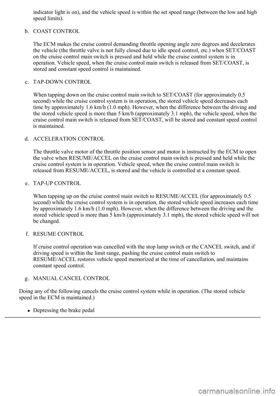
indicator light is on), and the vehicle speed is within the set speed range (between the low and high
speed limits).
b. COAST CONTROL
The ECM makes the cruise control demanding throttle opening angle zero degrees and decelerates
the vehicle (the throttle valve is not fully closed due to idle speed control, etc.) when SET/COAST
on the cruise control main switch is pressed and held while the cruise control system is in
operation. Vehicle speed, when the cruise control main switch is released from SET/COAST, is
stored and constant speed control is maintained.
c. TAP-DOWN CONTROL
When tapping down on the cruise control main switch to SET/COAST (for approximately 0.5
second) while the cruise control system is in operation, the stored vehicle speed decreases each
time by approximately 1.6 km/h (1.0 mph). However, when the difference between the driving and
the stored vehicle speed is more than 5 km/h (approximately 3.1 mph), the vehicle speed, when the
cruise control main switch is released from SET/COAST, will be stored and constant speed control
is maintained.
d. ACCELERATION CONTROL
The throttle valve motor of the throttle position sensor and motor is instructed by the ECM to open
<0057004b0048000300590044004f005900480003005a004b00480051000300350028003600380030002800120024002600260028002f00030052005100030057004b00480003004600550058004c005600480003004600520051005700550052004f000300
500044004c005100030056005a004c00570046004b0003004c[s pressed and held while the
cruise control system is in operation. Vehicle speed, when the cruise control main switch is
released from RESUME/ACCEL, is stored and the vehicle is controlled at a constant speed.
e. TAP-UP CONTROL
When tapping up on the cruise control main switch to RESUME/ACCEL (for approximately 0.5
second) while the cruise control system is in operation, the stored vehicle speed increases each time
by approximately 1.6 km/h (1.0 mph). However, when the difference between the driving and the
stored vehicle speed is more than 5 km/h (approximately 3.1 mph), the stored vehicle speed will not
be changed.
f. RESUME CONTROL
If cruise control operation was cancelled with the stop lamp switch or the CANCEL switch, and if
driving speed is within the limit range, pushing the cruise control main switch to
RESUME/ACCEL restores vehicle speed memorized at the time of cancellation, and maintains
constant speed control.
g. MANUAL CANCEL CONTROL
Doing any of the following cancels the cruise control system while in operation. (The stored vehicle
speed in the ECM is maintained.)
Depressing the brake pedal
Page 1917 of 4500
hand-held tester to the DLC3, turned the ignition switch to the ON position and operated the tester,
there is a problem on either the vehicle side or the tool side.
If communication is normal when the tool is connected to another vehicle, inspect the DLC3
on the original vehicle.
If communication is still impossible when the tool is connected to another vehicle, the
problem is probably in the tool itself, so consult the Service Department listed in the tool's
instruction manual.
3.CHECK THE INDICATOR
a. Turn the ignition switch to the ON position.
b. Check that the CRUISE main indicator light comes on when the cruise control main switch ON-
OFF button is push on, and that the indicator light goes off when the ON-OFF button is pushed off.
Fig. 13: Identifying CRUISE Main Indicator Light
Courtesy of TOYOTA MOTOR SALES, U.S.A., INC.
HINT:
If there is a problem with the indicator, inspect the CRUISE MAIN INDICATOR LIGHT CIRCUIT
.
HINT:
Page 1918 of 4500
If a malfunction occurs in the vehicle speed sensors, stop lamp switch assy, or other related parts during
cruise control driving, the ECM actuates AUTO CANCEL of the cruise control and then the CRUISE
main indicator light starts to blink, informing the driver of the malfunction. At the same time, data of the
malfunction is stored as a diagnostic trouble code (DTC).
Fig. 14: Identifying Blinking Pattern Of CRUISE Main Indicator Light
Courtesy of TOYOTA MOTOR SALES, U.S.A., INC.
1.DTC CHECK
a. Connect the hand-held tester to the DLC3.
b. Turn the ignition switch to the ON position.
c. Read the DTCs on the tester screen.
2.DTC CLEAR
Page 1921 of 4500

HINT:
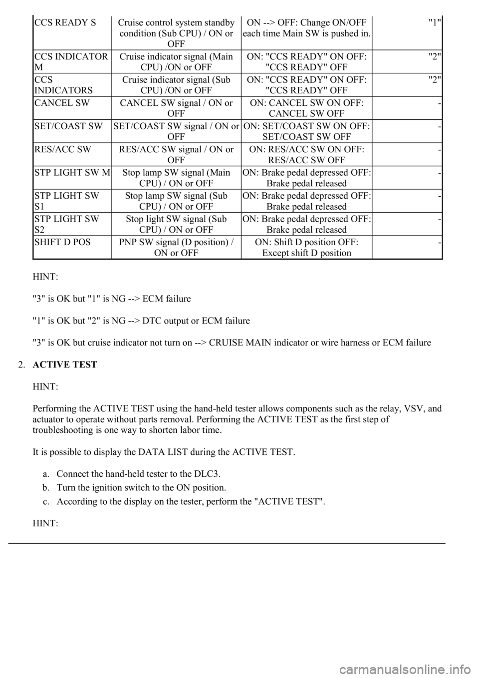
"3" is OK but "1" is NG --> ECM failure
"1" is OK but "2" is NG --> DTC output or ECM failure
"3" is OK but cruise indicator not turn on --> CRUISE MAIN indicator or wire harness or ECM failure
2.ACTIVE TEST
HINT:
Performing the ACTIVE TEST using the hand-held tester allows components such as the relay, VSV, and
actuator to operate without parts removal. Performing the ACTIVE TEST as the first step of
troubleshooting is one way to shorten labor time.
It is possible to display the DATA LIST during the ACTIVE TEST.
a. Connect the hand-held tester to the DLC3.
b. Turn the ignition switch to the ON position.
c. According to the display on the tester, perform the "ACTIVE TEST".
HINT:
CCS READY SCruise control system standby
condition (Sub CPU) / ON or
OFFON --> OFF: Change ON/OFF
each time Main SW is pushed in."1"
CCS INDICATOR
MCruise indicator signal (Main
CPU) /ON or OFFON: "CCS READY" ON OFF:
"CCS READY" OFF"2"
CCS
INDICATORSCruise indicator signal (Sub
CPU) /ON or OFFON: "CCS READY" ON OFF:
"CCS READY" OFF"2"
CANCEL SWCANCEL SW signal / ON or
OFFON: CANCEL SW ON OFF:
CANCEL SW OFF-
SET/COAST SWSET/COAST SW signal / ON or
OFFON: SET/COAST SW ON OFF:
SET/COAST SW OFF-
RES/ACC SWRES/ACC SW signal / ON or
OFFON: RES/ACC SW ON OFF:
RES/ACC SW OFF-
STP LIGHT SW MStop lamp SW signal (Main
CPU) / ON or OFFON: Brake pedal depressed OFF:
Brake pedal released-
STP LIGHT SW
S1Stop lamp SW signal (Sub
CPU) / ON or OFFON: Brake pedal depressed OFF:
Brake pedal released-
STP LIGHT SW
S2Stop light SW signal (Sub
CPU) / ON or OFFON: Brake pedal depressed OFF:
Brake pedal released-
SHIFT D POSPNP SW signal (D position) /
ON or OFFON: Shift D position OFF:
Except shift D position-
Page 1922 of 4500
The ignition switch must be turned to the ON position to proceed ACTIVE TEST using the hand-held
tester.
ACTIVE TEST DETAIL (COMBINATION METER ASSY)
HINT:
If a trouble code is displayed during the DTC check, check the circuit listed for that code. For details of each
code, refer to chart.
DIAGNOSTIC TROUBLE CODE CHART
Fig. 17: Diagnostic Trouble Code Information Chart
Courtesy of TOYOTA MOTOR SALES, U.S.A., INC.
CIRCUIT DESCRIPTION
See CIRCUIT DESCRIPTION
.
ItemVehicle Condition / Test DetailsDiagnostic Note
CRUISE INDIC"CRUISE" indicator is ON / OFF-
DTCDescription
DTC P0500 VEHICLE SPEED SENSOR CIRCUIT MALFUNCTION
DTC P0503 VEHICLE SPEED SENSOR CIRCUIT MALFUNCTION
DTC P0571 STOP LIGHT SWITCH CIRCUIT MALFUNCTION
DTC P0607 INPUT SIGNAL CIRCUIT MALFUNCTION
Page 1924 of 4500
Fig. 20: Wiring Diagram - Stop Light Switch Circuit Malfunction
Courtesy of TOYOTA MOTOR SALES, U.S.A., INC.
INSPECTION PROCEDURE
1.READ VALUE ON HAND-HELD TESTER
a. Connect the han
d-held tester to the DLC3.
Page 1925 of 4500

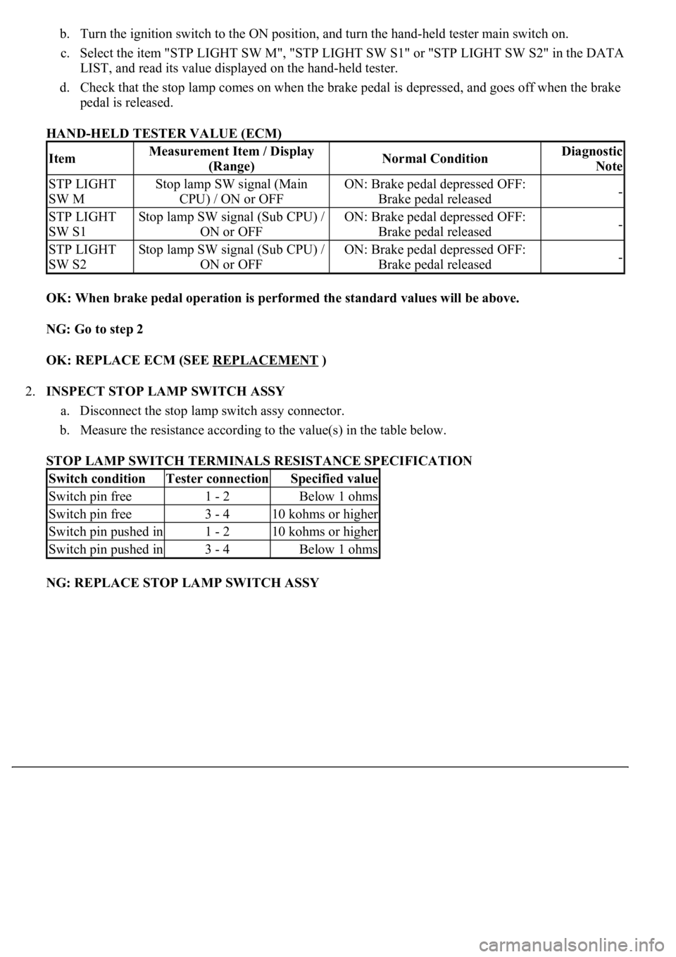
b. Turn the ignition switch to the ON position, and turn the hand-held tester main switch on.
c. Select the item "STP LIGHT SW M", "STP LIGHT SW S1" or "STP LIGHT SW S2" in the DATA
LIST, and read its value displayed on the hand-held tester.
d. Check that the stop lamp comes on when the brake pedal is depressed, and goes off when the brake
pedal is released.
HAND-HELD TESTER VALUE (ECM)
OK: When brake pedal operation is performed the standard values will be above.
NG: Go to step 2
OK: REPLACE ECM (SEE REPLACEMENT
)
2.INSPECT STOP LAMP SWITCH ASSY
a. Disconnect the stop lamp switch assy connector.
b. Measure the resistance according to the value(s) in the table below.
STOP LAMP SWITCH TERMINALS RESISTANCE SPECIFICATION
NG: REPLACE STOP LAMP SWITCH ASSY
ItemMeasurement Item / Display
(Range)Normal ConditionDiagnostic
Note
STP LIGHT
SW MStop lamp SW signal (Main
CPU) / ON or OFFON: Brake pedal depressed OFF:
Brake pedal released-
STP LIGHT
SW S1Stop lamp SW signal (Sub CPU) /
ON or OFFON: Brake pedal depressed OFF:
Brake pedal released-
STP LIGHT
SW S2Stop lamp SW signal (Sub CPU) /
ON or OFFON: Brake pedal depressed OFF:
Brake pedal released-
Switch conditionTester connectionSpecified value
Switch pin free1 - 2Below 1 ohms
Switch pin free3 - 410 kohms or higher
Switch pin pushed in1 - 210 kohms or higher
Switch pin pushed in3 - 4Below 1 ohms
Page 1940 of 4500
![LEXUS LS430 2003 Factory Repair Manual Fig. 31: [Disconnecting ECM Connector]
Courtesy of TOYOTA MOTOR SALES, U.S.A., INC.
NG: REPAIR OR REPLACE HARNESS OR CONNECTOR
OK: REPLACE ECM (SEE REPLACEMENT
)
CIRCUIT DESCRIPTION
The ECM det LEXUS LS430 2003 Factory Repair Manual Fig. 31: [Disconnecting ECM Connector]
Courtesy of TOYOTA MOTOR SALES, U.S.A., INC.
NG: REPAIR OR REPLACE HARNESS OR CONNECTOR
OK: REPLACE ECM (SEE REPLACEMENT
)
CIRCUIT DESCRIPTION
The ECM det](/manual-img/36/57050/w960_57050-1939.png)
Fig. 31: [Disconnecting ECM Connector]
Courtesy of TOYOTA MOTOR SALES, U.S.A., INC.
NG: REPAIR OR REPLACE HARNESS OR CONNECTOR
OK: REPLACE ECM (SEE REPLACEMENT
)
CIRCUIT DESCRIPTION
The ECM detects a cruise control switch signal and sends it to the combination meter via CAN and
BEAN. Then the CRUISE main indicator light comes on.
The CRUISE main indicator light circuit uses CAN and BEAN for communication. If there are any
malfunctions in this circuit, check for DTCs in the CAN communication system and multiplex
communication system.
INSPECTION PROCEDURE
1.PERFORM ACTIVE TEST BY HAND-HELD TESTER
a. Connect the hand-held tester to the DLC3.
b. Check the CRUISE main indicator light by using ACTIVE TEST.
ACTIVE TEST DETAIL (COMBINATION METER ASSY)
OK: Indicator light comes on/goes off.
NG: GO TO COMBINATION METER SYSTEM (SEE HOW TO PROCEED WITH
TROUBLESHOOTING )
OK: Go to next step
2.READ VALUE ON HAND-HELD TESTER
a. Connect the hand-held tester to the DLC3.
b. Turn the ignition switch to the ON position and turn the hand-held tester main switch on.
c. Select the item below in the "DATA LIST", and read the display on the hand-held tester.
DATA LIST (CC (ECM))
ItemVehicle Condition / Test DetailsDiagnostic Note
CRUISE INDIC"CRUISE" indicator is ON / OFF-
ItemMeasurement Item / Display
(Range)Normal ConditionDiagnostic
Note
CCS INDICATOR
MCruise indicator signal (Main
CPU) /ON or OFFON: "CCS READY" ON OFF:
"CCS READY" OFF-