Page 4307 of 4500
Fig. 117: Removing Cooler Air Duct No. 2
Courtesy of TOYOTA MOTOR SALES, U.S.A., INC.
25.REMOVE COOLING BOX ASSY
a. w/cooling box models:
Remove the 3 screws, clip and 2 ducts.
b. Disconnect the connector.
c. Remove the screw and cooling box light.
d. Remove the coolin
g box.
Page 4388 of 4500
Fig. 40: Installing Instrument Panel Air Bag Assy Lower No.1
Courtesy of TOYOTA MOTOR SALES, U.S.A., INC.
73.INSTALL SPIRAL CABLE SUB-ASSY (SEE REPLACEMENT
)
74.CENTER SPIRAL CABLE (SEE REPLACEMENT
)
75.INSTALL STEERING WHEEL ASSY (SEE OVERHAUL
)
76.STEERING WHEEL CENTER POINT
77.INSTALL HORN BUTTON ASSY (SEE OVERHAUL
)
78.CONNECT BATTERY NEGATIVE TERMINAL
79.INSPECT HORN BUTTON ASSY (SEE REPLACEMENT
)
80.INSPECT SRS WARNING LIGHT (SEE DIAGNOSIS SYSTEM
)
81.PERFORM INITIALIZATION (SEE INITIALIZATION
)
OVERHAUL
HINt:
Page 4445 of 4500

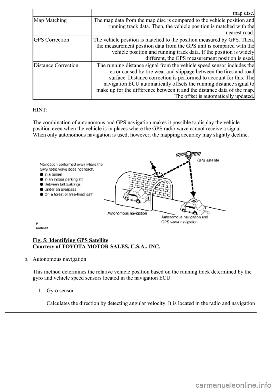
HINT:
The combination of autonomous and GPS navigation makes it possible to display the vehicle
position even when the vehicle is in places where the GPS radio wave cannot receive a signal.
<003a004b00480051000300520051004f005c000300440058005700520051005200500052005800560003005100440059004c004a00440057004c005200510003004c005600030058005600480047000f0003004b0052005a0048005900480055000f000300
57004b004800030050004400530053004c0051004a00030044[ccuracy may slightly decline.
Fig. 5: Identifying GPS Satellite
Courtesy of TOYOTA MOTOR SALES, U.S.A., INC.
b. Autonomous navigation
This method determines the relative vehicle position based on the running track determined by the
gyro and vehicle speed sensors located in the navigation ECU.
1. Gyro sensor
Calculates the direction b
y detecting angular velocity. It is located in the radio and navigation
map disc.
Map MatchingThe map data from the map disc is compared to the vehicle position and
running track data. Then, the vehicle position is matched with the
nearest road.
GPS CorrectionThe vehicle position is matched to the position measured by GPS. Then,
the measurement position data from the GPS unit is compared with the
vehicle position and running track data. If the position is widely
different, the GPS measurement position is used.
Distance CorrectionThe running distance signal from the vehicle speed sensor includes the
error caused by tire wear and slippage between the tires and road
surface. Distance correction is performed to account for this. The
navigation ECU automatically offsets the running distance signal to
make up for the difference between it and the distance data of the map.
The offset is automatically updated.