Page 4179 of 4500

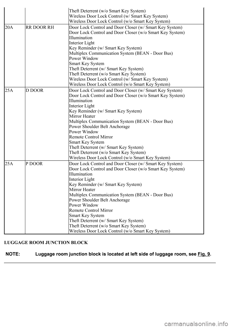
LUGGAGE ROOM JUNCTION BLOCK
Theft Deterrent (w/o Smart Key System)
Wireless Door Lock Control (w/ Smart Key System)
Wireless Door Lock Control (w/o Smart Key System)
20ARR DOOR RHDoor Lock Control and Door Closer (w/ Smart Key System)
Door Lock Control and Door Closer (w/o Smart Key System)
Illumination
Interior Light
Key Reminder (w/ Smart Key System)
Multiplex Communication System (BEAN - Door Bus)
Power Window
Smart Key System
Theft Deterrent (w/ Smart Key System)
Theft Deterrent (w/o Smart Key System)
Wireless Door Lock Control (w/ Smart Key System)
Wireless Door Lock Control (w/o Smart Key System)
25AD DOORDoor Lock Control and Door Closer (w/ Smart Key System)
Door Lock Control and Door Closer (w/o Smart Key System)
Illumination
Interior Light
Key Reminder (w/ Smart Key System)
Mirror Heater
Multiplex Communication System (BEAN - Door Bus)
Power Shoulder Belt Anchorage
Power Window
Remote Control Mirror
Smart Key System
Theft Deterrent (w/ Smart Key System)
Theft Deterrent (w/o Smart Key System)
Wireless Door Lock Control (w/o Smart Key System)
25AP DOORDoor Lock Control and Door Closer (w/ Smart Key System)
Door Lock Control and Door Closer (w/o Smart Key System)
Illumination
Interior Light
Key Reminder (w/ Smart Key System)
Mirror Heater
Multiplex Communication System (BEAN - Door Bus)
Power Shoulder Belt Anchorage
Power Window
Remote Control Mirror
Smart Key System
Theft Deterrent (w/ Smart Key System)
Theft Deterrent (w/o Smart Key System)
Wireless Door Lock Control (w/o Smart Key System)
Page 4181 of 4500
Fig. 10: Identifying Luggage Room Junction Block Components
Courtesy of TOYOTA MOTOR SALES, U.S.A., INC.
Luggage Room Junction Block
FuseSystem
7.5ALCE LPLight Auto Turn Off System
Page 4182 of 4500

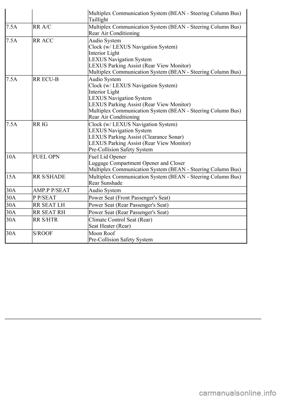
Multiplex Communication System (BEAN - Steering Column Bus)
Taillight
7.5ARR A/CMultiplex Communication System (BEAN - Steering Column Bus)
Rear Air Conditioning
7.5ARR ACCAudio System
Clock (w/ LEXUS Navigation System)
Interior Light
LEXUS Navigation System
LEXUS Parking Assist (Rear View Monitor)
Multiplex Communication System (BEAN - Steering Column Bus)
7.5ARR ECU-BAudio System
Clock (w/ LEXUS Navigation System)
Interior Light
LEXUS Navigation System
LEXUS Parking Assist (Rear View Monitor)
Multiplex Communication System (BEAN - Steering Column Bus)
Rear Air Conditioning
7.5ARR IGClock (w/ LEXUS Navigation System)
LEXUS Navigation System
LEXUS Parking Assist (Clearance Sonar)
LEXUS Parking Assist (Rear View Monitor)
Pre-Collision Safety System
10AFUEL OPNFuel Lid Opener
Luggage Compartment Opener and Closer
Multiplex Communication System (BEAN - Steering Column Bus)
15ARR S/SHADEMultiplex Communication System (BEAN - Steering Column Bus)
Rear Sunshade
30AAMP.P P/SEATAudio System
30AP P/SEATPower Seat (Front Passenger's Seat)
30ARR SEAT LHPower Seat (Rear Passenger's Seat)
30ARR SEAT RHPower Seat (Rear Passenger's Seat)
30ARR S/HTRClimate Control Seat (Rear)
Seat Heater (Rear)
30AS/ROOFMoon Roof
Pre-Collision Safety System
Page 4184 of 4500

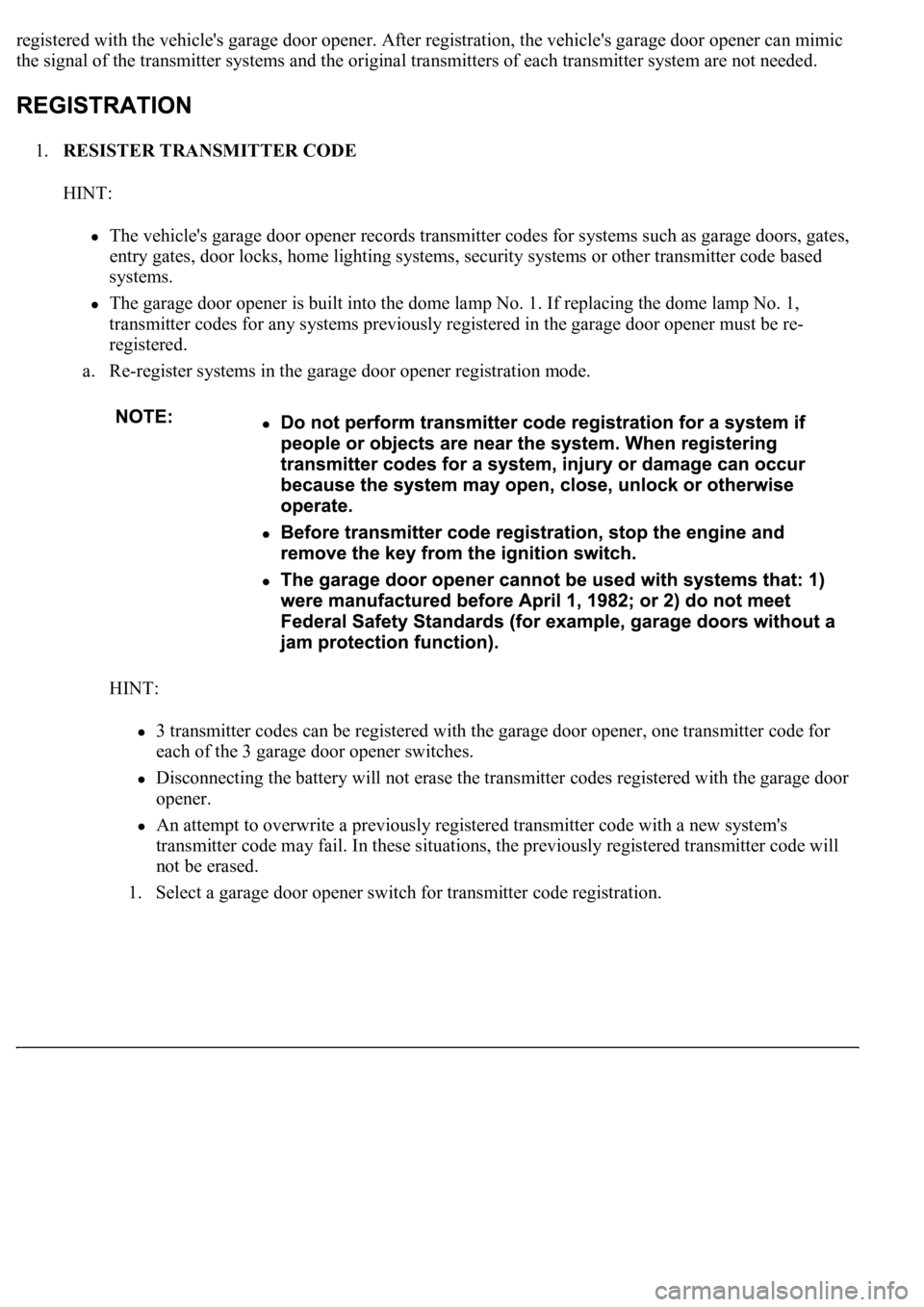
registered with the vehicle's garage door opener. After registration, the vehicle's garage door opener can mimic
the signal of the transmitter systems and the original transmitters of each transmitter system are not needed.
1.RESISTER TRANSMITTER CODE
HINT:
The vehicle's garage door opener records transmitter codes for systems such as garage doors, gates,
entry gates, door locks, home lighting systems, security systems or other transmitter code based
systems.
The garage door opener is built into the dome lamp No. 1. If replacing the dome lamp No. 1,
transmitter codes for any systems previously registered in the garage door opener must be re-
registered.
a. Re-register systems in the garage door opener registration mode.
HINT:
3 transmitter codes can be registered with the garage door opener, one transmitter code for
each of the 3 garage door opener switches.
Disconnecting the battery will not erase the transmitter codes registered with the garage door
opener.
An attempt to overwrite a previously registered transmitter code with a new system's
transmitter code may fail. In these situations, the previously registered transmitter code will
not be erased.
1. Select a
garage door opener switch for transmitter code registration.
Page 4201 of 4500
2.INSPECT REFRIGERANT PRESSURE WITH MANIFOLD GAUGE SET
a. This is a method in which trouble is located by using a manifold gauge set. Read the manifold
gauge pressure when these conditions are established.
Test conditions:
Temperature at the air inlet with the switch set at RECIRC is 30 to 35°C (86 to 95°F)
Engine is running at 2,000 rpm
Blower speed control switch is at "HI"
Temperature control dial is at "COOL"
HINT:
It should be noted that the gauge indications may vary slightly due to ambient temperature
conditions.
1. Normally functioning refrigeration system
Gauge reading:
Low pressure side: 0.15 to 0.25 MPa (1.5 to 2.5 kgf/cm
2 )
High pressure side: 1.37 to 1.57 MPa (14 to 16 kgf/cm
2 )
Page 4252 of 4500
Fig. 66: Checking Water Valve Operation
Courtesy of TOYOTA MOTOR SALES, U.S.A., INC.
35.ADJUST WATER VALVE CONTROL CABLE
a. Turn the ignition switch to the ON position.
b. Disconnect the control cable.
c. Set the temperature control switch to "MAX. COOL".
d. Set the water valve lever to the "COOL" position, connect the control cable and lock the clamp.
HINT:
Lock the clamp while lightly pushing the outer cable in the direction shown in Fig. 67
by an arrow.
Page 4258 of 4500
Installation is in the reverse order of removal.
See COMPONENTS .
1.DISCONNECT NEGATIVE TERMINAL CABLE FROM BATTERY
2.REMOVE FRONT DOOR SCUFF PLATE LH (See REPLACEMENT
)
3.REMOVE FRONT PILLAR GARNISH LH (See step 33 in REPLACEMENT
)
4.REMOVE INSTRUMENT PANEL UNDER COVER SUB-ASSY NO. 2 (See step 21 in
REPLACEMENT
)
5.REMOVE INSTRUMENT PANEL GARNISH SUB-ASSY RH (See step 22 in REPLACEMENT
)
6.REMOVE GLOVE COMPARTMENT DOOR ASSY W/ INSTRUMENT PANEL AIRBAG ASSY
LOWER NO. 2 (See step 25 in REPLACEMENT
)
7.REMOVE AIR SUSPENSION AND HEADLIGHT BEAM LEVEL CONTROL ECU
a. Disconnect the connectors.
b. Remove the 2 nuts and air suspension and headlight beam level control ECU.
8.REMOVE BLOWER ASSY
a. Disconnect the connectors.
b. Remove the nut and 3 bolts.
c. Remove the blower assy.
Page 4295 of 4500
INSPECTION
1.INSPECT REAR BLOWER MOTOR CIRCUIT (See REAR BLOWER MOTOR CIRCUIT
)
2.EXHAUST DAMPER CONTROL SERVOMOTOR CIRCUIT (See EXHAUST DAMPER
CONTROL SERVOMOTOR CIRCUIT )
3.INSPECT REAR MAGNETIC VALVE CIRCUIT (See REAR MAGNETIC VALVE CIRCUIT
)
4.INSPECT SMOKE SENSOR CIRCUIT (See SMOKE SENSOR CIRCUIT
)
5.INSPECT EVAPORATOR SUB-ASSY (REAR)
a. Check the evaporator sub-assy (rear) fins for blockage.
If the fins are clogged, clean them with compressed air.
b. Check the fitting for cracks or scratches.
If necessary, repair or replace.
6.INSPECT COOLING BOX LAMP SUB-ASSY
a. Connect positive (+) lead to terminal 1 and negative (-) lead to terminal 2.
b. Check that the cooling box lamp sub-assy comes on.
If coolin
g box light does not come on, replace the cooling box lamp sub-assy.