2003 LEXUS LS430 Absorber suspension
[x] Cancel search: Absorber suspensionPage 472 of 4500

a. The suspension control ECU operates the compressor & motor with the dryer and uses the solenoid
valves to control the vehicle height by analyzing the information based on the switches, sensors and
input signals.
b. Through the 4 height control sensors, the suspension control ECU detects the changes in the vehicle
height that results from the number of occupants or the amount of the load. Then, the suspension
control ECU controls the height control solenoid valves and the compressor & motor with the dryer
in order to automatically adjust the vehicle height to a constant (normal) level.
c. Furthermore, two vehicle heights can be selected by operating the height control switch: HI and
Normal.
d. In cases such as when the vehicle is jacked up, the auto leveling function is prohibited by turning
the ignition switch off.
If the vehicle is raised with its engine running, connect terminals OPB and CG of the DLC3 so the
vehicle height control is not carried out.
e. The absorber control switch selects the shock absorber damping force (normal or sport).
f. w/ Pre-collision safety system:
The suspension control ECU changes the stiffness of the suspension to the hardest setting by
receiving signals (collision unavoidable) from the cruise control ECU.
Function of Components
Page 476 of 4500

HINT:
By switching from normal mode into test mode, you can inspect the height control switch, absorber
control switch, front acceleration sensor and rear acceleration sensor.
When entering the test mode, the suspension control ECU sets all the test mode DTCs first.
After completing the test mode for each check item, the test mode DTCs that are determined
normal by the suspension control ECU will be erased.
The test mode DTCs for other check items may not be erased when only a certain signal is
inspected.
When the test mode returns back to the normal mode, all the test mode DTCs will be erased.
a. Procedure for Test Mode.
1. Make sure that the ignition switch is off.
2. Set each of the check items to the condition in Operation (A) in the Test mode table below.
3. Connect the hand-held tester to the DLC3.
4. Turn the ignition switch to the ON position.
5. Select the SIGNAL CHECK mode on the hand-held tester.
6. Set each of the check items to the condition in Operation (B) in the Test mode table below.
Page 480 of 4500
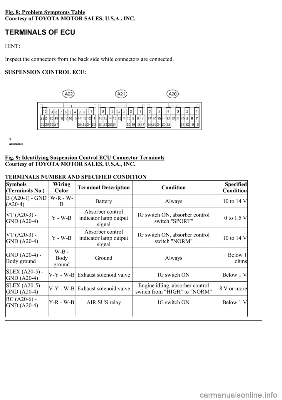
Fig. 8: Problem Symptoms Table
Courtesy of TOYOTA MOTOR SALES, U.S.A., INC.
HINT:
Inspect the connectors from the back side while connectors are connected.
SUSPENSION CONTROL ECU:
Fig. 9: Identifying Suspension Control ECU Connector Terminals
Courtesy of TOYOTA MOTOR SALES, U.S.A., INC.
TERMINALS NUMBER AND SPECIFIED CONDITION
Symbols
(Terminals No.)Wiring
ColorTerminal DescriptionConditionSpecified
Condition
B (A20-1) - GND
(A20-4)W-R - W-
BBatteryAlways10 to 14 V
VT (A20-3) -
GND (A20-4)Y - W-B
Absorber control
indicator lamp output
signalIG switch ON, absorber control
switch "SPORT"0 to 1.5 V
VT (A20-3) -
GND (A20-4)Y - W-B
Absorber control
indicator lamp output
signalIG switch ON, absorber control
switch "NORM"10 to 14 V
GND (A20-4) -
Body groundW-B -
Body
ground
GroundAlwaysBelow 1
ohms
SLEX (A20-5) -
GND (A20-4)V-Y - W-BExhaust solenoid valveIG switch ONBelow 1 V
SLEX (A20-5) -
GND (A20-4)V-Y - W-BExhaust solenoid valveEngine idling, absorber control
switch from "HIGH" to "NORM"8 V or more
RC (A20-6) -
GND (A20-4)Y-R - W-BAIR SUS relayIG switch ONBelow 1 V
Page 481 of 4500

RC (A20-6) -
GND (A20-4)Y-R - W-BAIR SUS relay
Engine idling, height control switch
from "NORM" to "HIGH" during
compressor operation
8 V or more
CANH (A20-7) -
CANL (A20-8)BR - YCAN communication
lineIG switch OFF54 to 67
ohms
SW1 (A20-9) -
GND (A20-4)O - W-BAbsorber control switch
input signalEngine idling, absorber control
switch "NORM" position10 to 14 V
SW1 (A20-9) -
GND (A20-4)O - W-BAbsorber control switch
input signalEngine idling, absorber control
switch "SPORT" position0 to 1.5 V
SIL (A20-13) -
GND (A20-4)W-G - W-
BDiagnosis tester
communication lineIG switch ONPulse
generation
TD (A20-14) -
GND (A20-4)L-B - W-BHeight control is not
operatingIG switch ON10 to 14 V
HSW (A20-15) -
GND (A20-4)LG-B - W-
BHeight control switch
input signalIG switch ON, height control
switch "NORM" position10 to 14 V
HSW (A20-15) -
GND (A20-4)LG-B - W-
BHeight control switch
input signalIG switch ON, height control
switch "HIGH" position0 to 1.5 V
SLFR (A20-16) -
GND (A20-4)G-W - W-
BHeight control solenoid
valve (FR)IG switch ONBelow 1 V
SLFR (A20-16) -
GND (A20-4)G-W - W-
BHeight control solenoid
valve (FR)Engine idling, height control switch
from "NORM" to "HIGH" or
reverse
8 V or more
SLFL (A20-17) -
GND (A20-4)R-W - W-
BHeight control solenoid
valve (FL)IG switch ONBelow 1 V
SLFL (A20-17) -
GND (A20-4)R-W - W-
BHeight control solenoid
valve (FL)Engine idling, height control switch
from "NORM" to "HIGH" or
reverse
8 V or more
SBL1 (A20-18) -
GND (A20-4)LG-R - W-
BHeight control sensor
power source (FL)IG switch ON4.5 to 5.5 V
VH (A20-19) -
GND (A20-4)P - W-BHeight control indicator
output signalIG switch ON, height control
switch "HIGH"0 to 1.5 V
SBR1 (A20-20) -
GND (A20-4)V-R - W-BHeight control indicator
output signalIG switch ON, height control
switch "NORM"10 to 14 V
SBR1 (A20-20) -
GND (A20-4)V-R - W-BHeight control sensor
power source (FR)IG switch ON4.5 to 5.5 V
SGR1 (A20-21) -
GND (A20-4)R-L - W-BHeight control sensor
ground (FR)AlwaysBelow 1
ohms
SGL1 (A20-22) -
GND (A20-4)LG-B - W-
BHeight control sensor
ground (FL)AlwaysBelow 1
ohms
FAR+ (A21-1) -
FAR- (A21-2)O - R-YSuspension control
actuator (FR)IG switch ONBelow 1
ohms
FBR+ (A21-3) -
FBR- (A21-4)R-G - L-GSuspension control
actuator (FR)IG switch ONBelow 1
ohms
FAL+ (A21-5) -
FAL- (A21-14)G-B - G-RSuspension control
actuator (FL)IG switch ONBelow 1
ohms
Page 485 of 4500
HINT:
If the hand-held tester display shows UNABLE TO CONNECT TO VEHICLE when the cable of
the hand-held tester is connected to the DLC3, the ignition switch is turned to the ON position and
the tester is operated, there is a problem either on the vehicle side or tester side.
If communication is normal when the tester is connected to another vehicle, inspect the
DLC3 on the original vehicle.
If communication is still not possible when the tester is connected to another vehicle, the
problem is probably in the tester itself, so consult the Service Department listed in the tester's
instruction manual.
c. Indicator lamp
1. During the vehicle height control operation, the absorber control indicator lamp blinks when
there is any malfunction in the air suspension system.
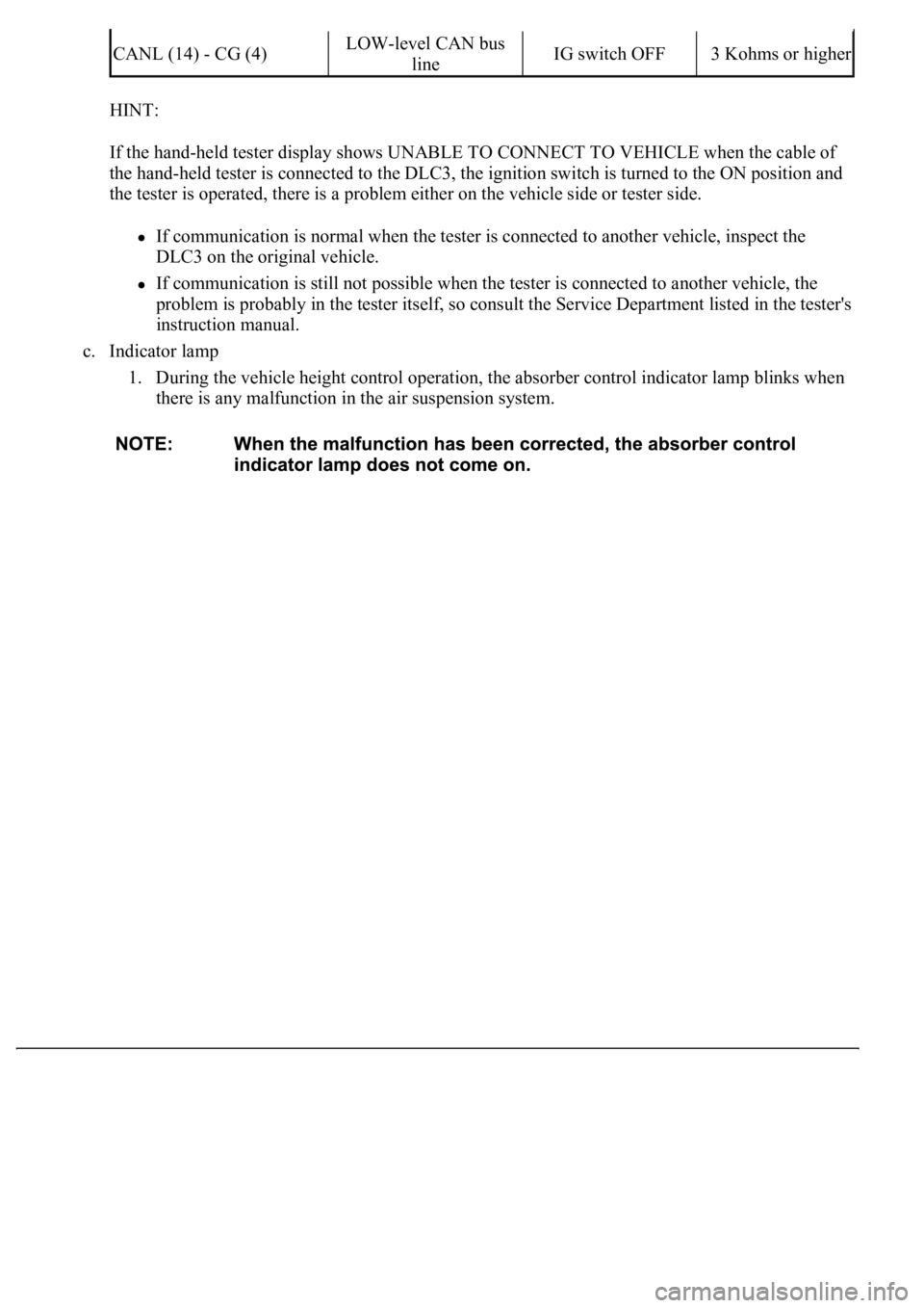
CANL (14) - CG (4)LOW-level CAN bus
lineIG switch OFF3 Kohms or higher
Page 486 of 4500

Fig. 11: Identifying Absorber Control Indicator Lamp Location (1 Of 2)
Courtesy of TOYOTA MOTOR SALES, U.S.A., INC.
d. DTCs (Normal mode)
1. DTCs are memorized in the suspension control ECU and read by using the hand-held tester
(SEE DTC CHECK/CLEAR
for the procedure of DTCs check).
e. Test mode
1. By switching from normal mode into test mode, you can inspect the height control switch,
absorber control switch, front acceleration sensor and rear acceleration sensor (SEE TEST
MODE PROCEDURE ).
2.CHECK INDICATOR LAMP
1. Turn the ignition switch to the ON position.
2. Check that the absorber control indicator lamp comes on for 2 seconds.
If the indicator check result is not normal, proceed to troubleshooting for the indicator lamp circuit.
TROUBLE AREA REFERENCE
Trouble AreaSee Procedure
Absorber control indicator lamp ABSORBER CONTROL INDICATOR LAMP
Page 492 of 4500

a. Connect the hand-held tester to the DLC3.
b. Turn the ignition switch to the ON position.
c. Following the display on the hand-held tester, perform the "ACTIVE TEST".
VEHICLE CONDITION / TEST DETAILS
HINT:
If an abnormality is not found when the parts are inspected, inspect the suspension control ECU.
If a trouble code is displayed during the DTC check, check the circuit listed for that code.
DIAGNOSTIC TROUBLE CODE CHART
ItemVehicle Condition / Test DetailsDiagnostic Note
DAMPER FRChanges damper step (Front Right) / min.: 1
step, max.: 17 stepShock absorber hardens as
damper step increases
DAMPER FLChanges damper step (Front Left) / min.: 1
step, max.: 17 stepShock absorber hardens as
damper step increases
DAMPER RRChanges damper step (Rear Right) / min.: 1
step, max.: 17 stepShock absorber hardens as
damper step increases
DAMPER RLChanges damper step (Rear Left) / min.: 1 step,
max.: 17 stepShock absorber hardens as
damper step increases
FR UP &
DOWNRight front vehicle height / UP or DOWN-
FL UP & DOWNLeft front vehicle height / UP or DOWN-
RR UP &
DOWNRight rear vehicle height / UP or DOWN-
RL UP &
DOWNLeft rear vehicle height / UP or DOWN-
FR SOLTurn OFF right front solenoid valve one
second after turning it ONOperation of solenoid (clicking
sound) can be heard
FL SOLTurn OFF left front solenoid valve one second
after turning it ONOperation of solenoid (clicking
sound) can be heard
RR SOLTurn OFF right rear solenoid valve one second
after turning it ONOperation of solenoid (clicking
sound) can be heard
RL SOLTurn OFF left rear solenoid valve one second
after turning it ONOperation of solenoid (clicking
sound) can be heard
MOTOR
RELAYAIR SUS relay / ON or OFFOperation of solenoid (clicking
sound) can be heard
DTCDescription
DTC C1711, DTC C1712, DTC C1713,
DTC C1714, DTC C1714
RIGHT FRONT HEIGHT CONTROL SENSOR
CIRCUIT
Page 495 of 4500

Fig. 17: Diagnostic Trouble Code Information Chart (2 Of 2)
Courtesy of TOYOTA MOTOR SALES, U.S.A., INC.
*1: For codes in the "Indicator Light" column with a "circ" mark, the absorber control indicator lamp blinks at 1
second intervals.
*2: For codes in the "Indicator Light" column with a " (xcirc)" mark, when trouble occurs, "HEIGHT HI" is
displayed on the multi-information display. Also, the master warning light is lit on the combination meter and
an alarm sounds.
*3: Since the relief pressure of the compressed air is 980 kPa (10 kgf/cm
2 , 142 psi), if vehicle height control is
attempted on a steeply sloping road, when the vehicle is overloaded, or when the vehicle height is jacked up
with the engine running, code "C1751" may be output and vehicle height control may be suspended. (This is not
abnormal.) In this case, however, when detecting the first error, approximately 10 minutes after the ignition
switch was turned to the ON position, vehicle height control is resumed. When the following errors are
detected, it takes 70 minutes until the control is resumed.
*4: If vehicle height control is operated while the wheels are removed or the vehicle is jacked up, code "C1752"
may be output, but this is not abnormal. When code "C1752" is output, vehicle height control is not carried out.
However, control is resumed if the ignition switch is turned off, then to the ON position again.
CIRCUIT DESCRIPTION
The height control sensor sub-assy controls the resistance value by following changes in vehicle height. The
suspension control ECU detects the change in vehicle height from the transformed voltage. The suspension
control ECU outputs a constant voltage of 5 V to the SHB terminal of the height control sensor sub-assy.
In the height control sensor, the voltage is changed due to resistance. The changed voltage is output from the