2003 LEXUS LS430 light
[x] Cancel search: lightPage 1775 of 4500
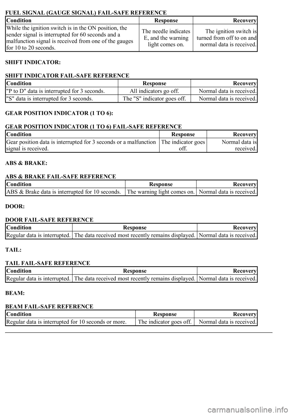
FUEL SIGNAL (GAUGE SIGNAL) FAIL-SAFE REFERENCE
SHIFT INDICATOR:
SHIFT INDICATOR FAIL-SAFE REFERENCE
GEAR POSITION INDICATOR (1 TO 6):
GEAR POSITION INDICATOR (1 TO 6) FAIL-SAFE REFERENCE
ABS & BRAKE:
ABS & BRAKE FAIL-SAFE REFERENCE
DOOR:
DOOR FAIL-SAFE REFERENCE
TAIL:
TAIL FAIL-SAFE REFERENCE
BEAM:
BEAM FAIL-SAFE REFERENCE
ConditionResponseRecovery
While the ignition switch is in the ON position, the
sender signal is interrupted for 60 seconds and a
malfunction signal is received from one of the gauges
for 10 to 20 seconds.The needle indicates
E, and the warning
light comes on.The ignition switch is
turned from off to on and
normal data is received.
ConditionResponseRecovery
"P to D" data is interrupted for 3 seconds.All indicators go off.Normal data is received.
"S" data is interrupted for 3 seconds.The "S" indicator goes off.Normal data is received.
ConditionResponseRecovery
Gear position data is interrupted for 3 seconds or a malfunction
signal is received.The indicator goes
off.Normal data is
received.
ConditionResponseRecovery
ABS & Brake data is interrupted for 10 seconds.The warning light comes on.Normal data is received.
ConditionResponseRecovery
Regular data is interrupted.The data received most recently remains displayed.Normal data is received.
ConditionResponseRecovery
Regular data is interrupted.The data received most recently remains displayed.Normal data is received.
ConditionResponseRecovery
<00350048004a0058004f00440055000300470044005700440003004c00560003004c00510057004800550055005800530057004800470003004900520055000300140013000300560048004600520051004700560003005200550003005000520055004800
11[The indicator goes off.Normal data is received.
Page 1776 of 4500
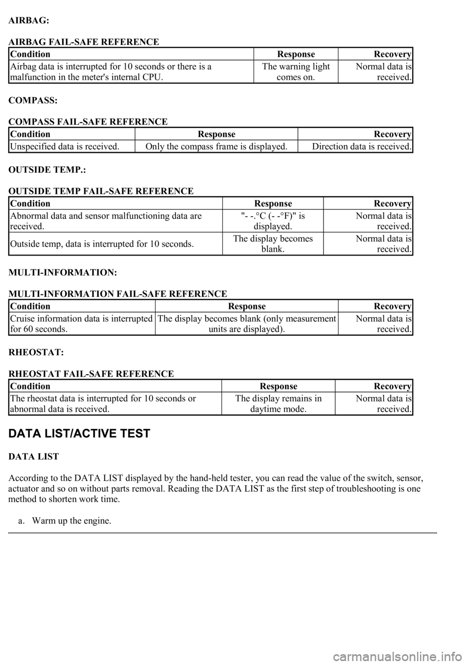
AIRBAG:
AIRBAG FAIL-SAFE REFERENCE
COMPASS:
COMPASS FAIL-SAFE REFERENCE
OUTSIDE TEMP.:
OUTSIDE TEMP FAIL-SAFE REFERENCE
MULTI-INFORMATION:
MULTI-INFORMATION FAIL-SAFE REFERENCE
RHEOSTAT:
RHEOSTAT FAIL-SAFE REFERENCE
DATA LIST
According to the DATA LIST displayed by the hand-held tester, you can read the value of the switch, sensor,
actuator and so on without parts removal. Reading the DATA LIST as the first step of troubleshooting is one
method to shorten work time.
a. Warm up the en
gine.
ConditionResponseRecovery
Airbag data is interrupted for 10 seconds or there is a
malfunction in the meter's internal CPU.The warning light
comes on.Normal data is
received.
ConditionResponseRecovery
Unspecified data is received.Only the compass frame is displayed.Direction data is received.
ConditionResponseRecovery
Abnormal data and sensor malfunctioning data are
received."- -.°C (- -°F)" is
displayed.Normal data is
received.
Outside temp, data is interrupted for 10 seconds.The display becomes
blank.Normal data is
received.
ConditionResponseRecovery
Cruise information data is interrupted
for 60 seconds.The display becomes blank (only measurement
units are displayed).Normal data is
received.
ConditionResponseRecovery
<0037004b004800030055004b004800520056005700440057000300470044005700440003004c00560003004c005100570048005500550058005300570048004700030049005200550003001400130003005600480046005200510047005600030052005500
03[
abnormal data is received.The display remains in
daytime mode.Normal data is
received.
Page 1780 of 4500
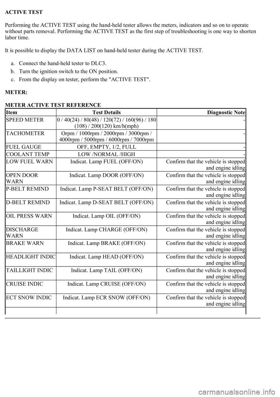
ACTIVE TEST
Performing the ACTIVE TEST using the hand-held tester allows the meters, indicators and so on to operate
without parts removal. Performing the ACTIVE TEST as the first step of troubleshooting is one way to shorten
labor time.
It is possible to display the DATA LIST on hand-held tester during the ACTIVE TEST.
a. Connect the hand-held tester to DLC3.
b. Turn the ignition switch to the ON position.
c. From the display on tester, perform the "ACTIVE TEST".
METER:
METER ACTIVE TEST REFERENCE
ItemTest DetailsDiagnostic Note
SPEED METER0 / 40(24) / 80(48) / 120(72) / 160(96) / 180
(108) / 200(120) km/h(mph)-
TACHOMETEROrpm / 1000rpm / 2000rpm / 3000rpm /
4000rpm / 5000rpm / 6000rpm / 7000rpm-
FUEL GAUGEOFF, EMPTY, 1/2, FULL-
COOLANT TEMPLOW /NORMAL /HIGH-
LOW FUEL WARNIndicat. Lamp FUEL (OFF/ON)Confirm that the vehicle is stopped
and engine idling
OPEN DOOR
WARNIndicat. Lamp DOOR (OFF/ON)Confirm that the vehicle is stopped
and engine idling
P-BELT REMINDIndicat. Lamp P-SEAT BELT (OFF/ON)Confirm that the vehicle is stopped
and engine idling
D-BELT REMINDIndicat. Lamp D-SEAT BELT (OFF/ON)Confirm that the vehicle is stopped
and engine idling
OIL PRESS WARNIndicat. Lamp OIL (OFF/ON)Confirm that the vehicle is stopped
and engine idling
DISCHARGE
WARNIndicat. Lamp CHARGE (OFF/ON)Confirm that the vehicle is stopped
and engine idling
BRAKE WARNIndicat. Lamp BRAKE (OFF/ON)Confirm that the vehicle is stopped
and engine idling
HEADLIGHT INDICIndicat. Lamp HEAD (OFF/ON)Confirm that the vehicle is stopped
and engine idling
TAILLIGHT INDICIndicat. Lamp TAIL (OFF/ON)Confirm that the vehicle is stopped
and engine idling
CRUISE INDICIndicat. Lamp CRUISE (OFF/ON)Confirm that the vehicle is stopped
and engine idling
ECT SNOW INDICIndicat. Lamp ECR SNOW (OFF/ON)Confirm that the vehicle is stopped
and engine idling
Page 1781 of 4500
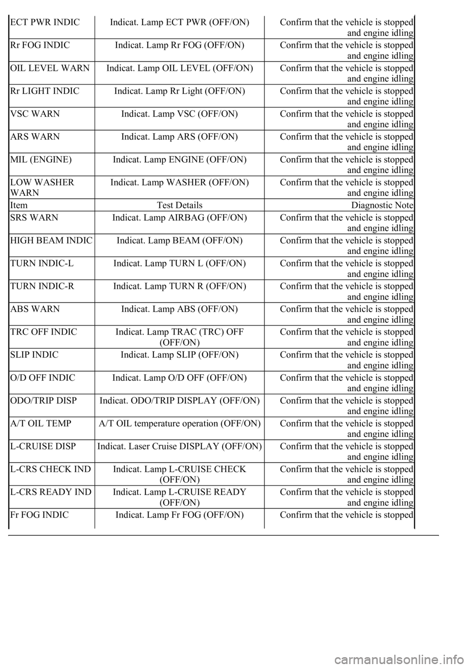
ECT PWR INDICIndicat. Lamp ECT PWR (OFF/ON)Confirm that the vehicle is stopped
and engine idling
Rr FOG INDICIndicat. Lamp Rr FOG (OFF/ON)Confirm that the vehicle is stopped
and engine idling
OIL LEVEL WARNIndicat. Lamp OIL LEVEL (OFF/ON)Confirm that the vehicle is stopped
and engine idling
Rr LIGHT INDICIndicat. Lamp Rr Light (OFF/ON)Confirm that the vehicle is stopped
and engine idling
VSC WARNIndicat. Lamp VSC (OFF/ON)Confirm that the vehicle is stopped
and engine idling
ARS WARNIndicat. Lamp ARS (OFF/ON)Confirm that the vehicle is stopped
and engine idling
MIL (ENGINE)Indicat. Lamp ENGINE (OFF/ON)Confirm that the vehicle is stopped
and engine idling
LOW WASHER
WARNIndicat. Lamp WASHER (OFF/ON)Confirm that the vehicle is stopped
and engine idling
ItemTest DetailsDiagnostic Note
SRS WARNIndicat. Lamp AIRBAG (OFF/ON)Confirm that the vehicle is stopped
and engine idling
HIGH BEAM INDICIndicat. Lamp BEAM (OFF/ON)Confirm that the vehicle is stopped
and engine idling
TURN INDIC-LIndicat. Lamp TURN L (OFF/ON)Confirm that the vehicle is stopped
and engine idling
TURN INDIC-RIndicat. Lamp TURN R (OFF/ON)Confirm that the vehicle is stopped
and engine idling
ABS WARNIndicat. Lamp ABS (OFF/ON)Confirm that the vehicle is stopped
and engine idling
TRC OFF INDICIndicat. Lamp TRAC (TRC) OFF
(OFF/ON)Confirm that the vehicle is stopped
and engine idling
SLIP INDICIndicat. Lamp SLIP (OFF/ON)Confirm that the vehicle is stopped
and engine idling
O/D OFF INDICIndicat. Lamp O/D OFF (OFF/ON)Confirm that the vehicle is stopped
and engine idling
ODO/TRIP DISPIndicat. ODO/TRIP DISPLAY (OFF/ON)Confirm that the vehicle is stopped
and engine idling
A/T OIL TEMPA/T OIL temperature operation (OFF/ON)Confirm that the vehicle is stopped
and engine idling
L-CRUISE DISPIndicat. Laser Cruise DISPLAY (OFF/ON)Confirm that the vehicle is stopped
and engine idling
L-CRS CHECK INDIndicat. Lamp L-CRUISE CHECK
(OFF/ON)Confirm that the vehicle is stopped
and engine idling
L-CRS READY INDIndicat. Lamp L-CRUISE READY
(OFF/ON)Confirm that the vehicle is stopped
and engine idling
Fr FOG INDICIndicat. Lamp Fr FOG (OFF/ON)Confirm that the vehicle is stopped
Page 1782 of 4500
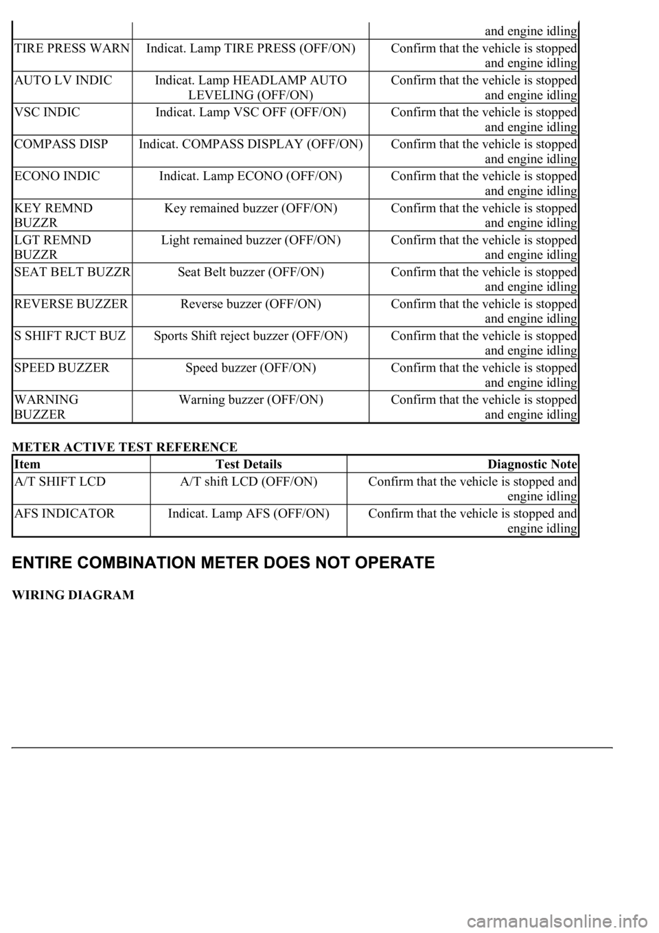
METER ACTIVE TEST REFERENCE
WIRING DIAGRAM
and engine idling
TIRE PRESS WARNIndicat. Lamp TIRE PRESS (OFF/ON)Confirm that the vehicle is stopped
and engine idling
AUTO LV INDICIndicat. Lamp HEADLAMP AUTO
LEVELING (OFF/ON)Confirm that the vehicle is stopped
and engine idling
VSC INDICIndicat. Lamp VSC OFF (OFF/ON)Confirm that the vehicle is stopped
and engine idling
COMPASS DISPIndicat. COMPASS DISPLAY (OFF/ON)Confirm that the vehicle is stopped
and engine idling
ECONO INDICIndicat. Lamp ECONO (OFF/ON)Confirm that the vehicle is stopped
and engine idling
KEY REMND
BUZZRKey remained buzzer (OFF/ON)Confirm that the vehicle is stopped
and engine idling
LGT REMND
BUZZRLight remained buzzer (OFF/ON)Confirm that the vehicle is stopped
and engine idling
SEAT BELT BUZZRSeat Belt buzzer (OFF/ON)Confirm that the vehicle is stopped
and engine idling
REVERSE BUZZERReverse buzzer (OFF/ON)Confirm that the vehicle is stopped
and engine idling
S SHIFT RJCT BUZSports Shift reject buzzer (OFF/ON)Confirm that the vehicle is stopped
and engine idling
SPEED BUZZERSpeed buzzer (OFF/ON)Confirm that the vehicle is stopped
and engine idling
WARNING
BUZZERWarning buzzer (OFF/ON)Confirm that the vehicle is stopped
and engine idling
ItemTest DetailsDiagnostic Note
A/T SHIFT LCDA/T shift LCD (OFF/ON)Confirm that the vehicle is stopped and
engine idling
AFS INDICATORIndicat. Lamp AFS (OFF/ON)Confirm that the vehicle is stopped and
engine idling
Page 1835 of 4500
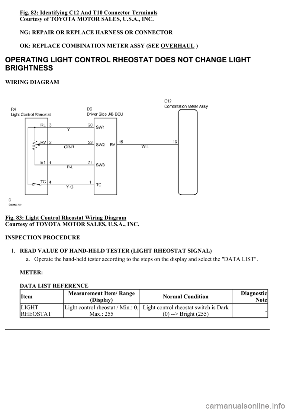
Fig. 82: Identifying C12 And T10 Connector Terminals
Courtesy of TOYOTA MOTOR SALES, U.S.A., INC.
NG: REPAIR OR REPLACE HARNESS OR CONNECTOR
OK: REPLACE COMBINATION METER ASSY (SEE OVERHAUL
)
WIRING DIAGRAM
Fig. 83: Light Control Rheostat Wiring Diagram
Courtesy of TOYOTA MOTOR SALES, U.S.A., INC.
INSPECTION PROCEDURE
1.READ VALUE OF HAND-HELD TESTER (LIGHT RHEOSTAT SIGNAL)
a. Operate the hand-held tester according to the steps on the display and select the "DATA LIST".
METER:
DATA LIST REFERENCE
ItemMeasurement Item/ Range
(Display)Normal ConditionDiagnostic
Note
LIGHT
RHEOSTATLight control rheostat / Min.: 0,
Max.: 255Light control rheostat switch is Dark
(0) --> Bright (255)-
Page 1836 of 4500
OK:
Light control can be changed within the specified range by actual operation.
NG: Go to step 2
OK: REPLACE COMBINATION METER ASSY (SEE OVERHAUL
)
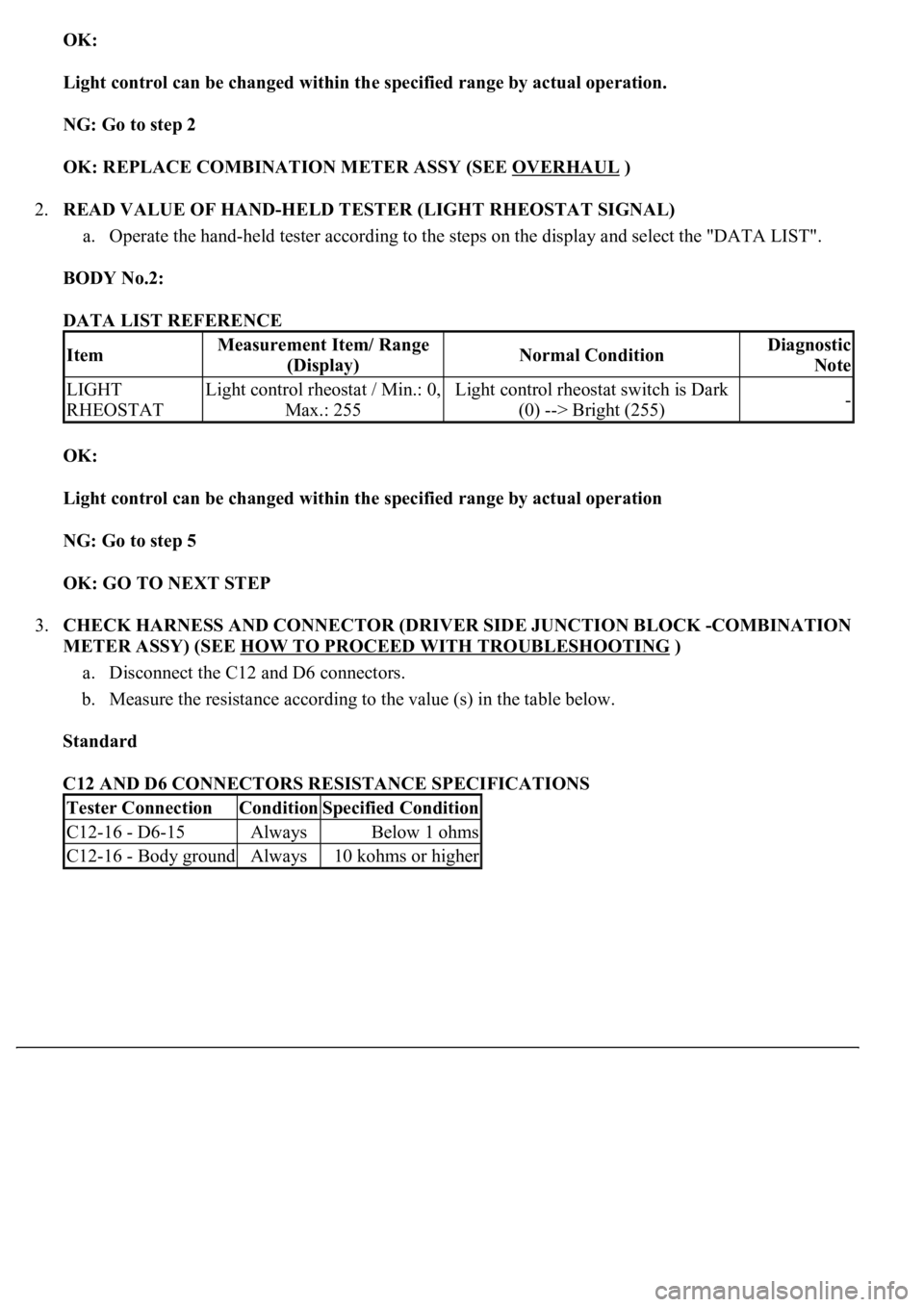
2.READ VALUE OF HAND-HELD TESTER (LIGHT RHEOSTAT SIGNAL)
a. Operate the hand-held tester according to the steps on the display and select the "DATA LIST".
BODY No.2:
DATA LIST REFERENCE
OK:
Light control can be changed within the specified range by actual operation
NG: Go to step 5
OK: GO TO NEXT STEP
3.CHECK HARNESS AND CONNECTOR (DRIVER SIDE JUNCTION BLOCK -COMBINATION
METER ASSY) (SEE HOW TO PROCEED WITH TROUBLESHOOTING
)
a. Disconnect the C12 and D6 connectors.
b. Measure the resistance according to the value (s) in the table below.
Standard
C12 AND D6 CONNECTORS RESISTANCE SPECIFICATIONS
ItemMeasurement Item/ Range
(Display)Normal ConditionDiagnostic
Note
LIGHT
RHEOSTATLight control rheostat / Min.: 0,
Max.: 255Light control rheostat switch is Dark
(0) --> Bright (255)-
Tester ConnectionConditionSpecified Condition
C12-16 - D6-15AlwaysBelow 1 ohms
C12-16 - Body groundAlways10 kohms or higher
Page 1838 of 4500
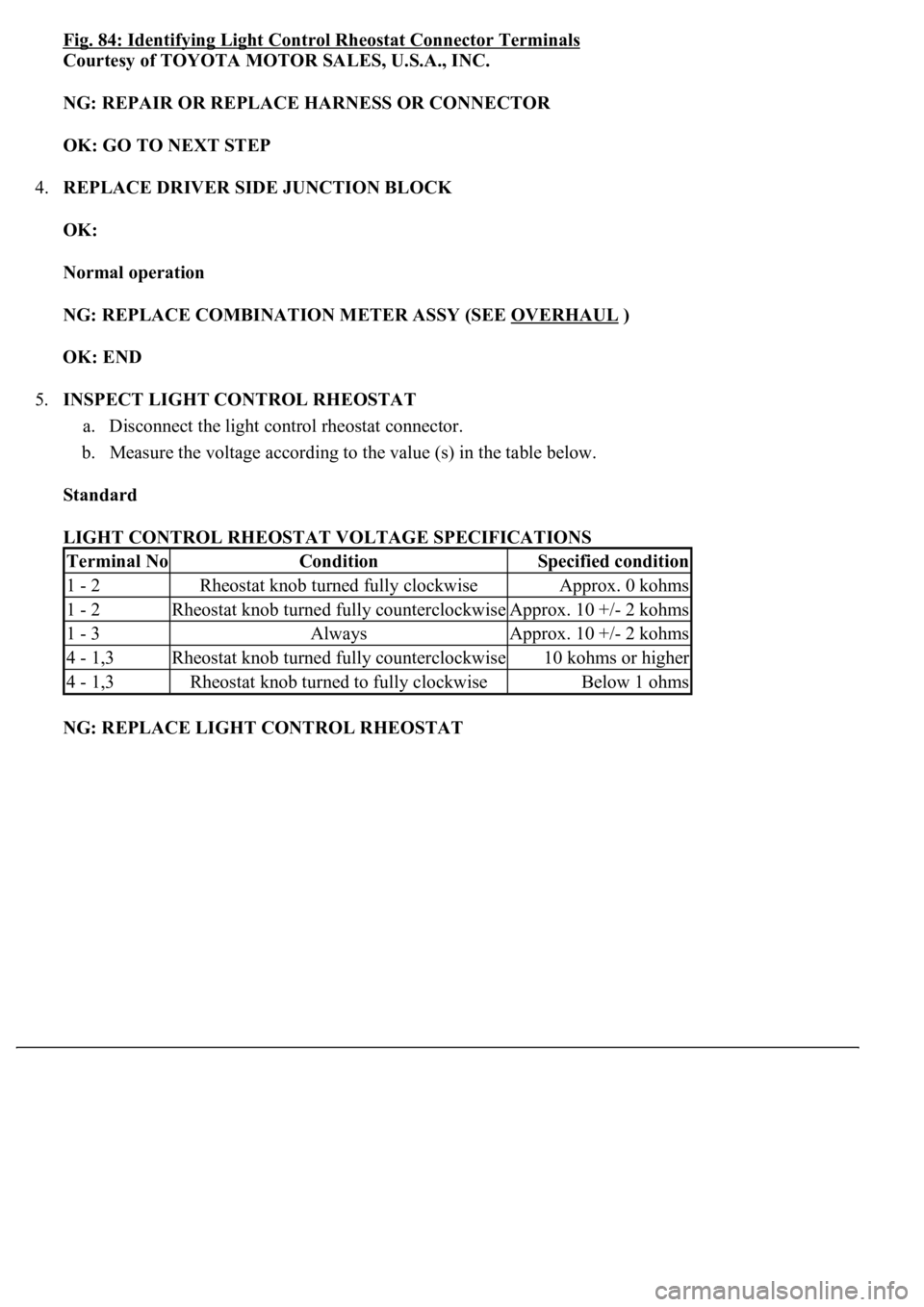
Fig. 84: Identifying Light Control Rheostat Connector Terminals
Courtesy of TOYOTA MOTOR SALES, U.S.A., INC.
NG: REPAIR OR REPLACE HARNESS OR CONNECTOR
OK: GO TO NEXT STEP
4.REPLACE DRIVER SIDE JUNCTION BLOCK
OK:
Normal operation
NG: REPLACE COMBINATION METER ASSY (SEE OVERHAUL
)
OK: END
5.INSPECT LIGHT CONTROL RHEOSTAT
a. Disconnect the light control rheostat connector.
b. Measure the voltage according to the value (s) in the table below.
Standard
LIGHT CONTROL RHEOSTAT VOLTAGE SPECIFICATIONS
NG: REPLACE LIGHT CONTROL RHEOSTAT
Terminal NoConditionSpecified condition
1 - 2Rheostat knob turned fully clockwiseApprox. 0 kohms
1 - 2Rheostat knob turned fully counterclockwiseApprox. 10 +/- 2 kohms
1 - 3AlwaysApprox. 10 +/- 2 kohms
4 - 1,3Rheostat knob turned fully counterclockwise10 kohms or higher
4 - 1,3Rheostat knob turned to fully clockwiseBelow 1 ohms