Page 704 of 4500
Fig. 2: Audio System Diagram
Courtesy of TOYOTA MOTOR SALES, U.S.A., INC.
Input and output signals of each ECU.
TRANSMITTING ECU (TRANSMITTER) CHART
1.CD (Compact Disc) player outline
a. A compact disc player uses a laser pickup to read digital signals recorded on a compact disc (CD).
Transmitting ECU
(Transmitter)
Receiving ECUSignalsCommunication method
Driver Side J/B ECUSteering Pad SwitchACC SW SignalBEAN (Column Bus)
Driver Side J/B ECUSteering Pad SwitchTaillight ON SignalBEAN (Column Bus)
Steering Pad SwitchRadio Receiver AssyAudio SignalBEAN (Column Bus) AVC-
LAN
Page 750 of 4500
HINT:
Confirm the noise conditions and inspect the appropriate noise filter.
First confirm that the foreign noise cannot be heard. Failure to do so will likely result in
misunderstanding the source of the noise.
If more than one source exists, noise should be removed from loudest to quietest.
NG: REINSTALL SPEAKER PROPERLY
OK: PROCEED TO NEXT CIRCUIT INSPECTION SHOWN IN PROBLEM SYMPTOMS
TABLE
INSPECTION PROCEDURE
1.CHECK THE CD
a. Check the CD.
OK: The CD is clean.
Noise can be heard when the brake pedal is depressed.Stop light switch
OthersStatic Electricity
Page 838 of 4500

<0029004c004a001100030014001c001d00030026005200510051004800460057004c0051004a00030029004f00520052005500030036004b004c004900570003002a00480044005500030036004b004c00490057004c0051004a0003003500520047000300
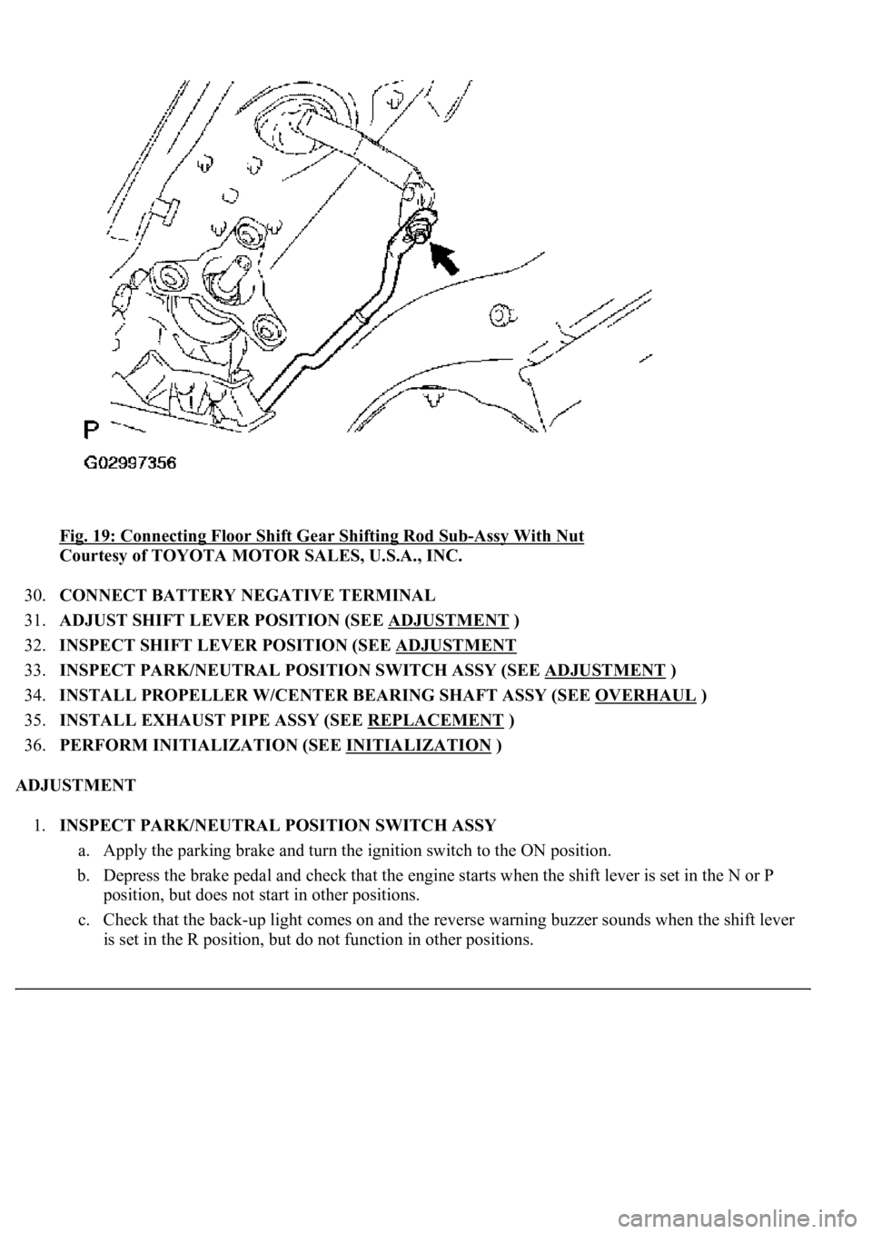
3600580045[-Assy With Nut
Courtesy of TOYOTA MOTOR SALES, U.S.A., INC.
30.CONNECT BATTERY NEGATIVE TERMINAL
31.ADJUST SHIFT LEVER POSITION (SEE ADJUSTMENT
)
32.INSPECT SHIFT LEVER POSITION (SEE ADJUSTMENT
33.INSPECT PARK/NEUTRAL POSITION SWITCH ASSY (SEE ADJUSTMENT
)
34.INSTALL PROPELLER W/CENTER BEARING SHAFT ASSY (SEE OVERHAUL
)
35.INSTALL EXHAUST PIPE ASSY (SEE REPLACEMENT
)
36.PERFORM INITIALIZATION (SEE INITIALIZATION
)
ADJUSTMENT
1.INSPECT PARK/NEUTRAL POSITION SWITCH ASSY
a. Apply the parking brake and turn the ignition switch to the ON position.
b. Depress the brake pedal and check that the engine starts when the shift lever is set in the N or P
position, but does not start in other positions.
c. Check that the back-up light comes on and the reverse warning buzzer sounds when the shift lever
is set in the R position, but do not function in other positions.
Page 929 of 4500

OVERHAUL
1.DISCONNECT BATTERY NEGATIVE TERMINAL
2.REMOVE INSTRUMENT PANEL UNDER COVER SUB-ASSY NO.2 (SEE REPLACEMENT
)
3.REMOVE CHOKE KNOB HOLE COVER (SEE REPLACEMENT
)
4.REMOVE GLOVE COMPARTMENT PLATE (SEE REPLACEMENT
)
5.REMOVE INSTRUMENT PANEL GARNISH SUB-ASSY LH (SEE REPLACEMENT
)
6.REMOVE INSTRUMENT PANEL FINISH PANEL (SEE REPLACEMENT
)
7.REMOVE INSTRUMENT CLUSTER FINISH PANEL (SEE REPLACEMENT
)
8.REMOVE INSTRUMENT PANEL FINISH PANEL LOWER CENTER (SEE REPLACEMENT
)
9.REMOVE PANEL INSTRUMENT CLUSTER FINISH LOWER (SEE REPLACEMENT
)
10.REMOVE INSTRUMENT PANEL UNDER COVER SUB-ASSY NO.1 (SEE REPLACEMENT
)
11.REMOVE COIN BOX ASSY (SEE REPLACEMENT
)
12.REMOVE INSTRUMENT CLUSTER FINISH PANEL CENTER LOWER (SEE
REPLACEMENT
)
13.REMOVE CIGAR LIGHTER HOLE BEZEL (SEE REPLACEMENT
)
14.REMOVE INSTRUMENTAL CLUSTER FINISH PANEL END (SEE REPLACEMENT
)
15.REMOVE INSTRUMENT PANEL SAFETY PAD SUB-ASSY NO.1 (SEE REPLACEMENT
)
16.REMOVE REAR CONSOLE ARMREST ASSY (SEE REPLACEMENT
)
17.REMOVE CONSOLE BOX PLATE (SEE REPLACEMENT
)
18.REMOVE INSTRUMENT PANEL CUP HOLDER ASSY (SEE REPLACEMENT
)
19.REMOVE CONSOLE BOX (SEE REPLACEMENT
)
20.REMOVE CONSOLE BOX DUCT NO.1 (SEE REPLACEMENT
)
21.SEPARATE FLOOR SHIFT GEAR SHIFTING ROD SUB-ASSY
a. Remove the nut and separate the floor shift gear shifting rod sub-assy.
22.REMOVE FLOOR SHIFT ASSY
a. Disconnect the connector.
b. Disconnect the indoor electrical key oscillator connector. (w/smart key)
Page 961 of 4500
Fig. 136: Removing Nut And Disconnecting Shifting Rod From Connecting Rod Swivel
Courtesy of TOYOTA MOTOR SALES, U.S.A., INC.
b. Turn the control shaft lever of the neutral start switch counterclockwise until it stops, and turn it
clockwise 2 notches to set it to the N position.
c. Move the shift lever to the N position and tighten the nut while lightly pushing the lever toward the
R position.
d. After adjustment, check that the shift lever moves smoothly and the shift lever and gear operate
correctl
y.
Page 1005 of 4500

34.CHECK AND ADJUST BRAKE PEDAL HEIGHT (SEE ON-VEHICLE INSPECTION )
35.CHECK PEDAL FREE PLAY (SEE ON
-VEHICLE INSPECTION )
36.CHECK PEDAL RESERVE DISTANCE (SEE ON
-VEHICLE INSPECTION )
37.INSTALL COMBINATION METER ASSY (SEE OVERHAUL
)
38.INSTALL INSTRUMENT CLUSTER FINISH PANEL (SEE REPLACEMENT
)
39.INSTALL INSTRUMENT PANEL UNDER COVER SUB-ASSY NO.2 (SEE REPLACEMENT
)
40.INSTALL INSTRUMENT PANEL AIR BAG ASSY LOWER NO.1 (SEE REPLACEMENT
)
41.INSTALL INSTRUMENT PANEL SAFETY PAD SUB-ASSY NO.1 (SEE REPLACEMENT
)
42.INSTALL OUTER MIRROR SWITCH ASSY
43.INSTALL COIN BOX ASSY
44.INSTALL INSTRUMENT PANEL UNDER COVER SUB-ASSY NO.1 (SEE REPLACEMENT
)
45.INSTALL INSTRUMENT CLUSTER FINISH PANEL CENTER LOWER
46.INSTALL INSTRUMENT CLUSTER FINISH PANEL END
47.INSTALL TURN SIGNAL SWITCH ASSY (SEE REPLACEMENT
)
48.INSTALL SPIRAL CABLE SUB-ASSY (SEE REPLACEMENT
)
49.INSTALL STEERING COLUMN COVER (SEE OVERHAUL
)
50.INSTALL STEERING WHEEL ASSY (SEE OVERHAUL
)
<00360036003700030013001c001c001800130010001800130013001400160003000b0013001c001c00180014001000130018001300140013000f00030013001c001c00180015001000130018001300140013000f00030013001c001c001800160010001300
18001300150013000f00030013001c001c0018001700100013[5021)
51.INSTALL HORN BUTTON ASSY (SEE OVERHAUL
)
52.INSTALL STEERING WHEEL COVER LOWER NO.2
53.INSTALL SWITCH & VOLUME CASE
54.CONNECT BATTERY NEGATIVE TERMINAL
55.INSPECT SRS WARNING LIGHT (SEE DIAGNOSIS SYSTEM
)
56.PERFORM INITIALIZATION (SEE PRECAUTION
)
OVERHAUL
1.REMOVE ENGINE ROOM SIDE COVER
2.SEPARATE ENGINE ROOM NO.3 R/B
a. Remove the bolt and separate the engine room No.3 R/B.
3.DRAIN BRAKE FLUID
a. Draw out fluid with syringe.
4.REMOVE BRAKE MASTER CYLINDER SUB-ASSY
a. Remove the clamp from the 2 brake tubes.
Page 1011 of 4500
Fig. 44: Removing Snap Ring With Snap Ring Pliers
Courtesy of TOYOTA MOTOR SALES, U.S.A., INC.
d. Place a shop rag and 2 wooden blocks on the work table, and lightly tap the cylinder flange against
the block edges until the No.2 piston drops out of the cylinder.
<002500480003004600440055004800490058004f00030051005200570003005700520003005600460055004400570046004b00030057004b0048000300500044005600570048005500030046005c004f004c00510047004800550003004500520055004800
110003[
HINT:
Make sure that the distance (A) from the shop rag to the top of the blocks is at least 100 mm (3.94
in.).
e. Remove the O-rin
g from the master cylinder body.
Page 1014 of 4500
Fig. 47: Installing Snap Ring
Courtesy of TOYOTA MOTOR SALES, U.S.A., INC.
10.INSTALL MASTER CYLINDER RESERVOIR GROMMET
a. Apply lithium soap base glycol grease to the 2 master cylinder reservoir grommets.
b. Install the 2 master cylinder reservoir grommets to the master cylinder reservoir sub-assy.
11.INSTALL BRAKE MASTER CYLINDER RESERVOIR SUB-ASSY
a. Install the master cylinder reservoir sub-assy to the master cylinder sub-assy with the set screw.
b. Install the master cylinder reservoir strainer and master cylinder reservoir filler cap.
c. Connect the brake fluid warning switch connector.
12.INSPECT AND ADJUST BRAKE BOOSTER PUSH ROD
a. Depress the brake pedal several times while the engine is stopped to release the pressure.
b. Set SST on the brake master cylinder sub-assy and lower the pin of the SST until it slightly touches
the piston.
c. Apply chalk to the flat surfaced tip of the SST pin.
SST 09737-00013