Page 2832 of 4323

INSTALLATION
1. INSTALL WATER PUMP
(a) Install a n")
CO0IT±06
B04463
Connect
New O±Ring
B03030
Seal Width
2 ± 3 mm
New O±Ring
CO±8
± COOLINGWATER PUMP
2824 Author�: Date�:
2005 SEQUOIA (RM1146U)
INSTALLATION
1. INSTALL WATER PUMP
(a) Install a new O±ring to the water bypass pipe end.
(b) Apply soapy water to the O±ring.
(c) Connect the water pump to the water bypass pipe end.
(d) Install the water pump and a new gasket with the 5 bolts,
2 stud bolts and nut. Uniformly tighten the bolts, stud bolts
and nut in several passes.
Torque:
Bolt: 21 N´m (215 kgf´cm, 15 ft´lbf)
Stud bolt and nut: 18 N´m (185 kgf´cm, 13 ft´lbf)
2. INSTALL WATER INLET AND INLET HOUSING AS-
SEMBLY
(a) Remove any old packing (FIPG) material and be careful
not to drop any oil on the contact surfaces of the water in-
let housing and water pump.
�Using a razor blade and gasket scraper, remove all
the old packing (FIPG) material from the gasket sur-
faces and sealing groove.
�Thoroughly clean all components to remove all the
loose material.
�Using a non±residue solvent, clean both sealing
surfaces.
(b) Apply seal packing to the sealing groove of water inlet
housing as shown in the illustration.
Seal packing: Part No. 08826±00100 or equivalent
�Install a nozzle that has been cut to a 2 ± 3 mm (0.08
± 0.12 in.) opening.
�Parts must be assembled within 3 minutes of ap-
plication. Otherwise the material must be removed
and reapplied.
�Immediately remove nozzle from the tube and rein-
stall cap.
(c) Install a new O±ring to the water inlet housing.
(d) Apply soapy water on the O±ring.
(e) Attach the water inlet housing end to the front water by-
pass joint hole.
Page 2934 of 4323
AT13B±01
F17895
Steering Wheel Pad
Steering
Wheel
Column Lower
CoverCombination
SwitchSteering Column Assembly
Transmission Control
Cable Assembly
Lower LH Finish PanelColumn Hole
Cover No. 2
No. 2 Universal
Joint Assembly
No. 2 Heater to Register Dust Torx® Screw
35 (360, 26)
35 (360, 26)
8.0 (82, 71 in.´lbf)
26 (260, 19)
26 (260, 19)
8.8 (90, 78 in.´lbf)
50 (510, 37)
8.8 (90, 78 in.´lbf)
Front Door Scuff PlateCowl Side Trim
Hood Lock
Release Lever
8.0 (82, 71 in.´lbf)
Side Panel
No. 2 lntermediate
Shaft AssemblyBrake Pedal
Return Spring
Column Upper Cover
N´m (kgf´cm, ft´lbf): Specified torque
Steering Wheel Lower
No. 3 Cover
Steering Wheel Lower
No. 2 Cover
35 (360, 26)
Siding Yoke
Torx® Screw AT±18
± AUTOMATIC TRANSMISSION (A750E, A750F)COLUMN SHIFT ASSEMBLY
2926 Author�: Date�:
2005 SEQUOIA (RM1146U)
COLUMN SHIFT ASSEMBLY
COMPONENTS
Page 3005 of 4323

TROUBLESHOOTING
PROBLEM SYMPTOMS TABLE
Use the table below to help you find the cause of the problem")
SA140±10
± SUSPENSION AND AXLETROUBLESHOOTING
SA±1
2997 Author�: Date�:
2005 SEQUOIA (RM1146U)
TROUBLESHOOTING
PROBLEM SYMPTOMS TABLE
Use the table below to help you find the cause of the problem. The numbers indicate the priority of the likely
cause of the problem. Check each part in order. If necessary, replace these parts.
SymptomSuspect AreaSee page
Bottoming
1. Vehicle (Overloaded)
2. Spring (Weak)
3. Shock absorber (Worn)±
SA±63
SA±135
SA±66
SA±135
Sways/pitches
1. Tire (Worn or improperly inflated)
2. Stabilizer bar (Bent or broken)
3. Shock absorber (Worn)SA±3
SA±90
SA±149
SA±66
SA±135
Front wheel shimmy
1. Tire (Worn or improperly inflated)
2. Wheel (Out of balance)
3. Shock absorber (Worn)
4. Wheel alignment (Incorrect)
5. Ball joints (Worn)
6. Hub bearing (Loose or worn)
7. Steering linkage (Loose or worn)
8. Steering gear (Out of adjustment or broken)SA±3
SA±3
SA±66
SA±4
SA±83
SA±88
SA±21
±
SR±37
Abnormal tire wear
1. Tire (Improperly inflated)
2. Wheel alignment (Incorrect)
3. Shock absorber (Worn)
4. Suspension parts (Worn)SA±3
SA±4
SA±66
SA±139
±
Noise in front differential
1. Oil level (Low or wrong grade)
2. Excessive backlash between pinion and ring gear
3. Ring, pinion or side gear (Worn or chipped)
4. Pinion shaft bearing (Worn)
5. Side bearing (Worn)
6. Differential bearing (Loose or worn)SA±38
SA±50
SA±50
SA±50
SA±50
SA±50
Oil leak from front differential
1. Oil level (Too high or wrong grade)
2. Front differential rear oil seal (Worn or damaged)
3. Side gear oil seal (Worn or damaged)
4. Companion flange (Loose or damaged)
5. Side gear shaft (Damaged)SA±38
SA±38
SA±50
SA±50
SA±50
Noise in rear axle
1. Oil level (Low or wrong grade)
2. Excessive backlash between pinion and ring gear
3. Ring, pinion or side gear (Worn or chipped)
4. Pinion shaft bearing (Worn)
5. Axle shaft bearing (Worn)
6. Differential bearing (Loose or worn)SA±105
SA±109
SA±109
SA±109
SA±94
SA±109
Oil leak from rear axle1. Oil seal (Worn or damaged)
2. Rear axle housing (Cracked)SA±94
±
Oil leak from rear differential
1. Oil level (Too high or wrong grade)
2. Oil seal (Worn or damaged)
3. Companion flange (Loose or damaged)SA±105
SA±105
SA±109
Page 3007 of 4323
(B)
R07928
± SUSPENSION AND AXLETIRE AND WHEEL
SA±3
2999 Author�: Date�:
2005 SEQUOIA (RM1146U)
TIRE AND WHEEL
INSPECTION
1. INSPECT TIRE
(a) Check the tires for")
SA17H±11
R03031
F13676
Front (A)(B)
R07928
± SUSPENSION AND AXLETIRE AND WHEEL
SA±3
2999 Author�: Date�:
2005 SEQUOIA (RM1146U)
TIRE AND WHEEL
INSPECTION
1. INSPECT TIRE
(a) Check the tires for wear and proper inflation pressure.
Cold tire inflation pressure:
Tire sizeFront
kPa (kgf/cm2, psi)
Rear
kPa (kgf/cm2, psi)
P245/70R16220 (2.2, 32)240 (2.4, 35)
P265/70R16220 (2.2, 32)220 (2.2, 32)
P265/65R17220 (2.2, 32)220 (2.2, 32)
(b) Using a dial indicator, check the tire runout.
Tire runout: 3.0 mm (0.118 in.) or less
2. ROTATING TIRE
HINT:
�Rotate tires as shown in the illustration.
�Rotate as shown in (B) if the spare tire is included in the
rotation.
3. INSPECT WHEEL BALANCE
(a) Check and adjust the Off±the±car balance.
(b) If necessary, check and adjust the On±the±car balance.
Imbalance after adjustment: 14.0 g (0.031 lb) or less
4. CHECK FRONT SUSPENSION FOR LOOSENESS
5. CHECK STEERING LINKAGE FOR LOOSENESS
6. CHECK BALL JOINT FOR LOOSENESS
7. CHECK SHOCK ABSORBER WORKS PROPERLY
�Check if oil leaks.
�Check the mounting bushings for wear.
�Bounce front and rear of the vehicle.
Page 3026 of 4323
SA23I±04
R13426
F07263
F07264
F07265
SA±22
± SUSPENSION AND AXLEFRONT AXLE HUB
3018 Author�: Date�:
2005 SEQUOIA (RM1146U)
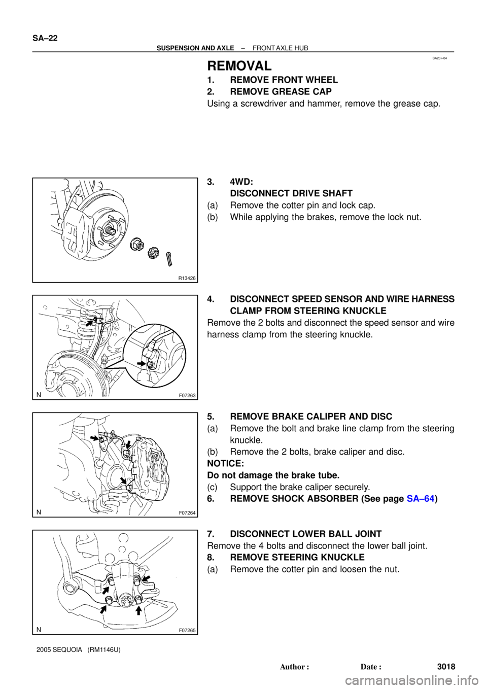
REMOVAL
1. REMOVE FRONT WHEEL
2. REMOVE GREASE CAP
Using a screwdriver and hammer, remove the grease cap.
3. 4WD:
DISCONNECT DRIVE SHAFT
(a) Remove the cotter pin and lock cap.
(b) While applying the brakes, remove the lock nut.
4. DISCONNECT SPEED SENSOR AND WIRE HARNESS
CLAMP FROM STEERING KNUCKLE
Remove the 2 bolts and disconnect the speed sensor and wire
harness clamp from the steering knuckle.
5. REMOVE BRAKE CALIPER AND DISC
(a) Remove the bolt and brake line clamp from the steering
knuckle.
(b) Remove the 2 bolts, brake caliper and disc.
NOTICE:
Do not damage the brake tube.
(c) Support the brake caliper securely.
6. REMOVE SHOCK ABSORBER (See page SA±64)
7. DISCONNECT LOWER BALL JOINT
Remove the 4 bolts and disconnect the lower ball joint.
8. REMOVE STEERING KNUCKLE
(a) Remove the cotter pin and loosen the nut.
Page 3032 of 4323

INSTALLATION
1. INSTALL STEERING KNUCKLE
(a) 4WD:
Insert the drive shaft into the axle hub and temp")
SA23J±05
SA±28
± SUSPENSION AND AXLEFRONT AXLE HUB
3024 Author�: Date�:
2005 SEQUOIA (RM1146U)
INSTALLATION
1. INSTALL STEERING KNUCKLE
(a) 4WD:
Insert the drive shaft into the axle hub and temporarily tighten the nut.
NOTICE:
Be careful not to damage the oil seal and drive shaft boot.
(b) Connect the steering knuckle to the upper suspension arm.
(c) Install the nut and a new cotter pin.
If the holes for the cotter pin are not aligned, tighten the nut further up to 60°.
Torque: 105 N´m (1,100 kgf´cm, 77 ft´lbf)
2. CONNECT LOWER BALL JOINT
Connect the lower ball joint to the steering knuckle with the 4 bolts.
Torque: 65 N´m (663 kgf´cm, 48 ft´lbf)
3. INSTALL SHOCK ABSORBER (See page SA±70)
4. INSTALL BRAKE CALIPER
(a) Install the disc, brake caliper and 2 bolts.
Torque: 123 N´m (1,250 kgf´cm, 90 ft´lbf)
(b) Install the brake line clamp to the steering knuckle with the bolt.
Torque: 28 N´m (285 kgf´cm, 21 ft´lbf)
5. CONNECT SPEED SENSOR AND WIRE HARNESS CLAMP
Connect the speed sensor and wire harness clamp to the steering knuckle with the 2 bolts.
Torque: 8.0 N´m (82 kgf´cm, 71 ft´lbf)
6. 4WD:
INSTALL DRIVE SHAFT LOCK NUT
(a) While applying the brakes, tighten the nut.
Torque: 235 N´m (2,400 kgf´cm, 173 ft´lbf)
(b) Install the lock cap and a new cotter pin.
If the holes for the cotter pin are not aligned, tighten the nut further up to 60°.
7. INSTALL GREASE CAP
8. INSTALL FRONT WHEEL
Torque: 110 N´m (1,150 kgf´cm, 83 ft´lbf)
9. DEPRESS BRAKE PEDAL SEVERAL TIMES
10. CHECK FRONT WHEEL ALIGNMENT (See page SA±4)
11. CHECK SPEED SENSOR SIGNAL (See page DI±899)
12. PERFORM ZERO POINT CALIBRATION OF STEERING ANGLE, MASTER CYLINDER PRES-
SURE, YAW RATE AND DECELERATION SENSORS (See page DI±897)
Page 3034 of 4323
SA14E±08
F06645
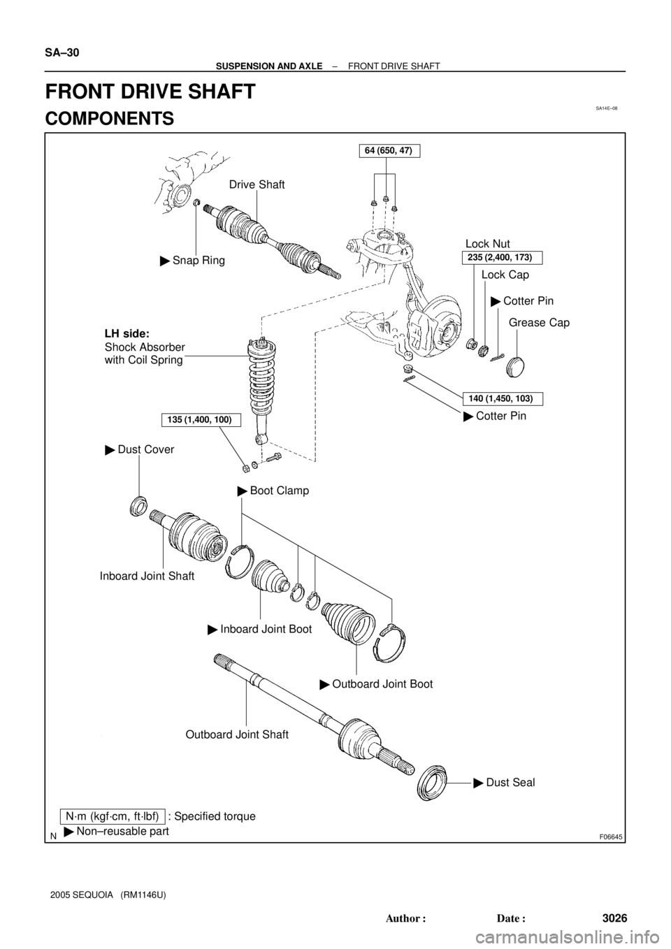
� Snap Ring
Drive Shaft
� Dust Cover
Inboard Joint Shaft
� Inboard Joint Boot
� Outboard Joint Boot
� Boot Clamp
� Dust Seal Outboard Joint Shaft
� Cotter Pin� Cotter Pin
Grease Cap Lock Cap Lock Nut
235 (2,400, 173)
140 (1,450, 103)
� Non±reusable part
N´m (kgf´cm, ft´lbf) : Specified torqueShock Absorber
with Coil Spring
135 (1,400, 100)
LH side:
64 (650, 47)
SA±30
± SUSPENSION AND AXLEFRONT DRIVE SHAFT
3026 Author�: Date�:
2005 SEQUOIA (RM1146U)
FRONT DRIVE SHAFT
COMPONENTS
Page 3035 of 4323
SA24L±03
F06624
R12863
SST
R13233
± SUSPENSION AND AXLEFRONT DRIVE SHAFT
SA±31
3027 Author�: Date�:
2005 SEQUOIA (RM1146U)
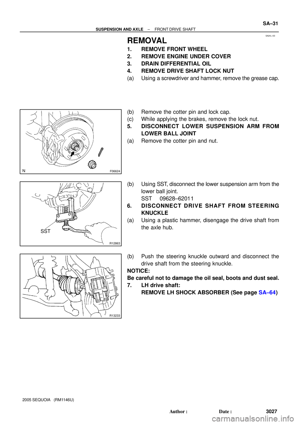
REMOVAL
1. REMOVE FRONT WHEEL
2. REMOVE ENGINE UNDER COVER
3. DRAIN DIFFERENTIAL OIL
4. REMOVE DRIVE SHAFT LOCK NUT
(a) Using a screwdriver and hammer, remove the grease cap.
(b) Remove the cotter pin and lock cap.
(c) While applying the brakes, remove the lock nut.
5. DISCONNECT LOWER SUSPENSION ARM FROM
LOWER BALL JOINT
(a) Remove the cotter pin and nut.
(b) Using SST, disconnect the lower suspension arm from the
lower ball joint.
SST 09628±62011
6. DISCONNECT DRIVE SHAFT FROM STEERING
KNUCKLE
(a) Using a plastic hammer, disengage the drive shaft from
the axle hub.
(b) Push the steering knuckle outward and disconnect the
drive shaft from the steering knuckle.
NOTICE:
Be careful not to damage the oil seal, boots and dust seal.
7. LH drive shaft:
REMOVE LH SHOCK ABSORBER (See page SA±64)