Page 3092 of 4323
SA246±04
R12777
SA±88
± SUSPENSION AND AXLEFRONT LOWER BALL JOINT
3084 Author�: Date�:
2005 SEQUOIA (RM1146U)
INSPECTION
1. INSPECT LOWER BALL JOINT BOOT FOR DAMAGE
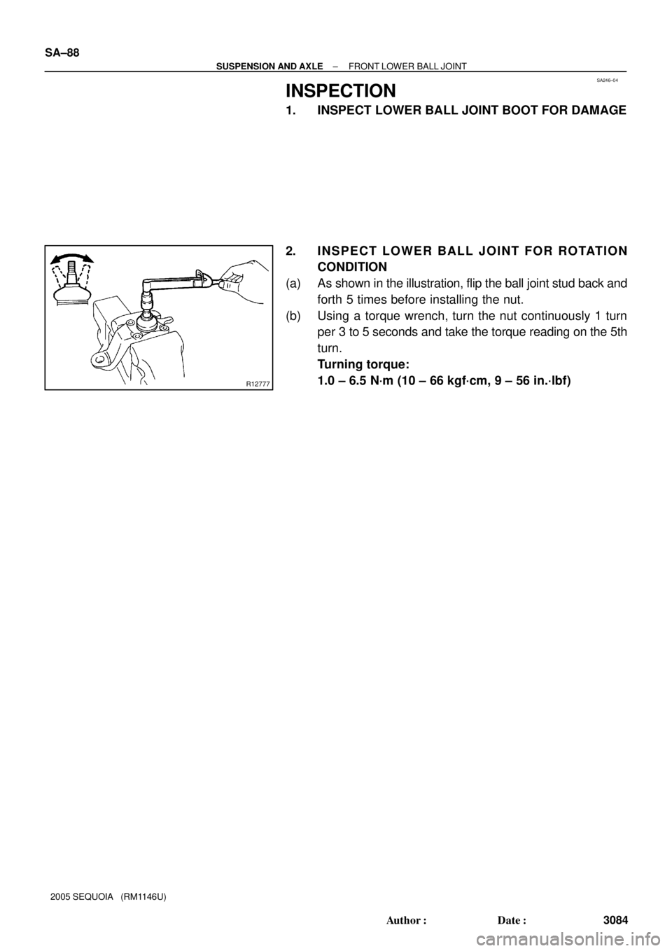
2. INSPECT LOWER BALL JOINT FOR ROTATION
CONDITION
(a) As shown in the illustration, flip the ball joint stud back and
forth 5 times before installing the nut.
(b) Using a torque wrench, turn the nut continuously 1 turn
per 3 to 5 seconds and take the torque reading on the 5th
turn.
Turning torque:
1.0 ± 6.5 N´m (10 ± 66 kgf´cm, 9 ± 56 in.´lbf)
Page 3093 of 4323

INSTALLATION
1. INSTALL LOWER BALL JOINT
(a) While lifting the upper suspension arm and stee")
SA247±07
± SUSPENSION AND AXLEFRONT LOWER BALL JOINT
SA±89
3085 Author�: Date�:
2005 SEQUOIA (RM1146U)
INSTALLATION
1. INSTALL LOWER BALL JOINT
(a) While lifting the upper suspension arm and steering knuckle, install the lower ball joint.
(b) Temporarily install the 4 bolts to the lower ball joint.
(c) Install the set nut to hold the lower ball joint to the lower suspension arm and a new cotter pin.
Torque: 159 N´m (1,621 kgf´cm, 117 ft´lbf)
If the holes for the cotter pin are not aligned, tighten the nut further up to 60°.
2. CONNECT TIE ROD END
Connect the tie rod end to the lower ball joint with the nut and a new cotter pin.
Torque: 91 N´m (930 kgf´cm, 67 ft´lbf)
If the holes for the cotter pin are not aligned, tighten the nut further up to 60°.
3. TIGHTEN LOWER BALL JOINT SET 4 BOLTS
Torque: 65 N´m (663 kgf´cm, 48 ft´lbf)
4. INSTALL FRONT WHEEL
Torque: 110 N´m (1,150 kgf´cm, 83 ft´lbf)
5. CHECK FRONT WHEEL ALIGNMENT (See page SA±4)
6. PERFORM ZERO POINT CALIBRATION OF STEERING ANGLE, MASTER CYLINDER PRES-
SURE, YAW RATE AND DECELERATION SENSORS (See page DI±897)
Page 3095 of 4323
SA24O±02
W01738
F07266
R12778
± SUSPENSION AND AXLEFRONT STABILIZER BAR
SA±91
3087 Author�: Date�:
2005 SEQUOIA (RM1146U)
REMOVAL
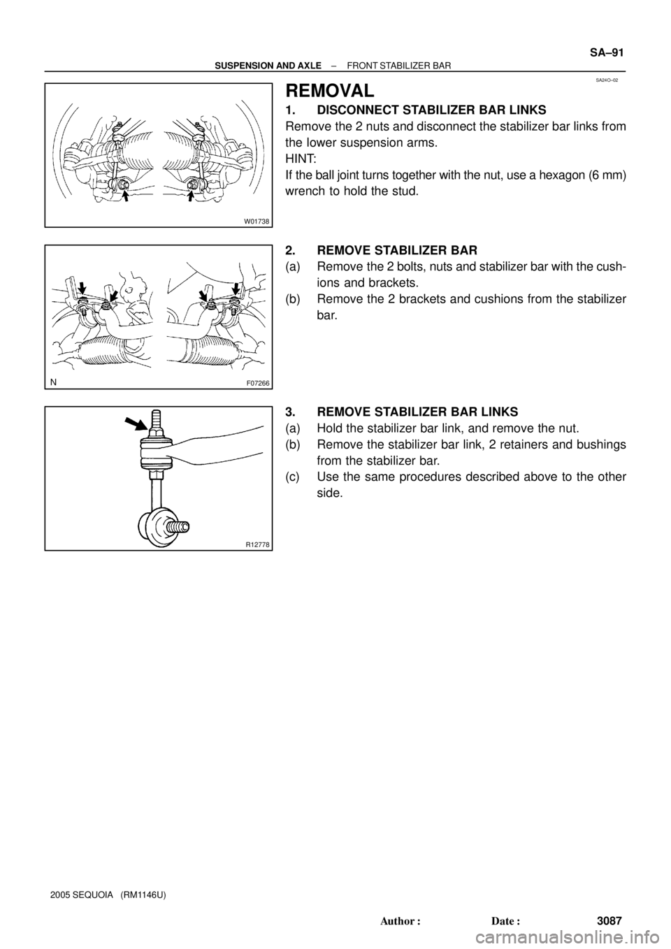
1. DISCONNECT STABILIZER BAR LINKS
Remove the 2 nuts and disconnect the stabilizer bar links from
the lower suspension arms.
HINT:
If the ball joint turns together with the nut, use a hexagon (6 mm)
wrench to hold the stud.
2. REMOVE STABILIZER BAR
(a) Remove the 2 bolts, nuts and stabilizer bar with the cush-
ions and brackets.
(b) Remove the 2 brackets and cushions from the stabilizer
bar.
3. REMOVE STABILIZER BAR LINKS
(a) Hold the stabilizer bar link, and remove the nut.
(b) Remove the stabilizer bar link, 2 retainers and bushings
from the stabilizer bar.
(c) Use the same procedures described above to the other
side.
Page 3096 of 4323
SA248±03
Z00340
SA±92
± SUSPENSION AND AXLEFRONT STABILIZER BAR
3088 Author�: Date�:
2005 SEQUOIA (RM1146U)
INSPECTION
1. INSPECT STABILIZER BAR LINK BALL JOINT BOOT
FOR DAMAGE
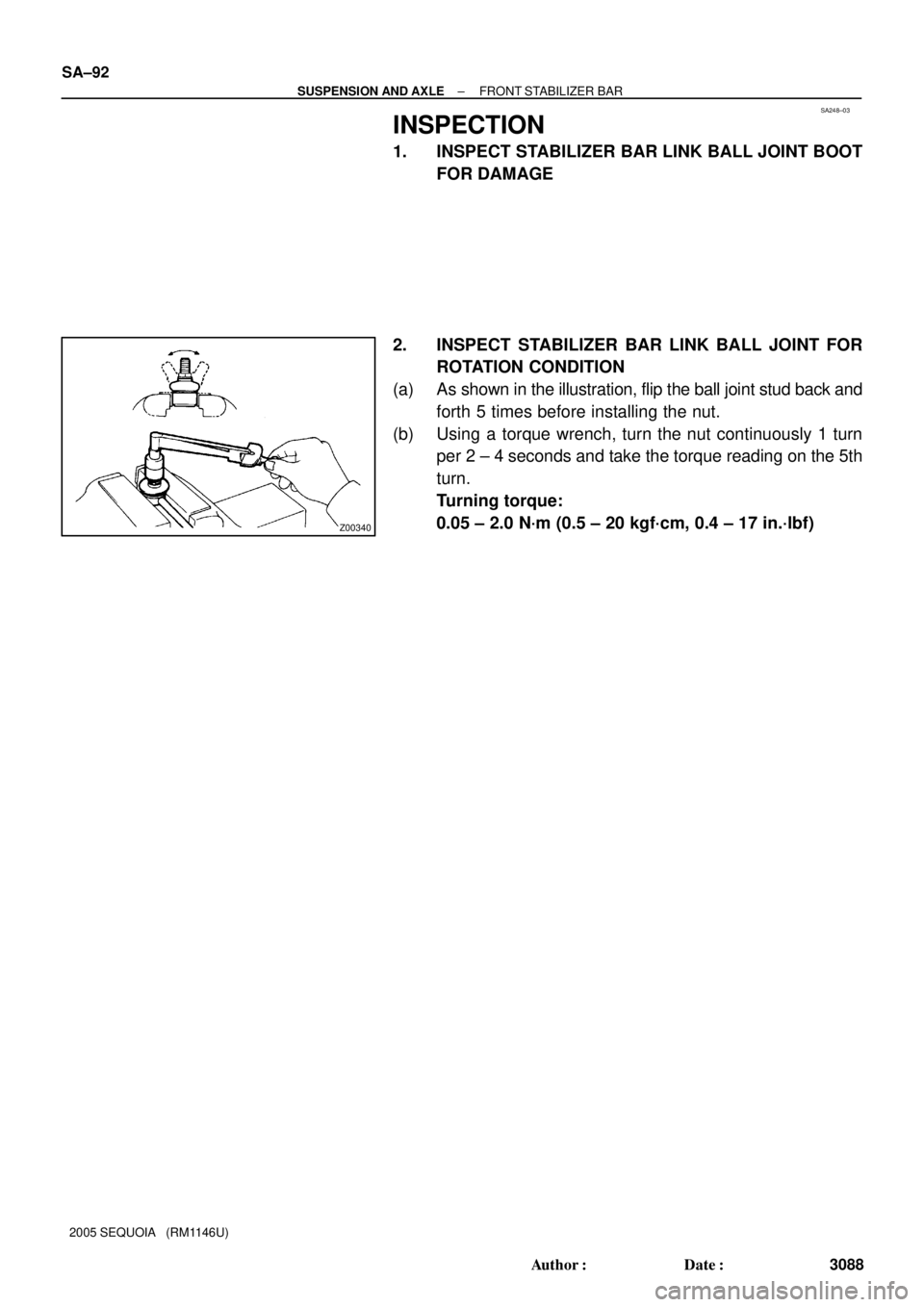
2. INSPECT STABILIZER BAR LINK BALL JOINT FOR
ROTATION CONDITION
(a) As shown in the illustration, flip the ball joint stud back and
forth 5 times before installing the nut.
(b) Using a torque wrench, turn the nut continuously 1 turn
per 2 ± 4 seconds and take the torque reading on the 5th
turn.
Turning torque:
0.05 ± 2.0 N´m (0.5 ± 20 kgf´cm, 0.4 ± 17 in.´lbf)
Page 3097 of 4323
SA249±03
F07266
Cutout
± SUSPENSION AND AXLEFRONT STABILIZER BAR
SA±93
3089 Author�: Date�:
2005 SEQUOIA (RM1146U)
INSTALLATION
1. INSTALL STABILIZER BAR LINKS
(a) Install the 2 bushings, retainers and stabilizer bar link to
the stabilizer bar.
(b) Hold the stabilizer bar link, and install a new nut.
Torque: 19 N´m (190 kgf´cm, 14 ft´lbf)
(c) Use the same procedures described above to the other
side.
2. INSTALL STABILIZER BAR
(a) Install the 2 bushings with their cutout facing to the rear-
ward of the stabilizer bar.
(b) Install the stabilizer bar and 2 brackets with the nuts and
bolts.
Torque: 37 N´m (377 kgf´cm, 27 ft´lbf)
3. CONNECT STABILIZER BAR LINKS TO LOWER SUS-
PENSION ARM
Torque: 69 N´m (700 kgf´cm, 51 ft´lbf)
HINT:
If the ball joint turns together with the nut, use a hexagon (6 mm)
wrench to hold the nut.
Page 3154 of 4323
SA17F±04
F14302
F14303
SA±150
± SUSPENSION AND AXLEREAR STABILIZER BAR
3146 Author�: Date�:
2005 SEQUOIA (RM1146U)
REMOVAL
1. REMOVE REAR WHEELS
Torque: 110 N´m (1,150 kgf´cm, 83 ft´lbf)
2. SUPPORT REAR AXLE HOUSING WITH JACK
3. REMOVE STABILIZER BAR LINKS
(a) Remove the 2 nuts and stabilizer bar link.
Torque: 69 N´m (704 kgf´cm, 51 ft´lbf)
HINT:
If the ball joint stud turns together with the nut, use a hexagon
wrench to hold the stud.
(b) Use the same procedure described above to the other
side.
4. REMOVE STABILIZER BAR FROM REAR AXLE
HOUSING
(a) Remove the 4 bolts and stabilizer bar with the bushings
and brackets.
Torque: 37 N´m (377 kgf´cm, 27 ft´lbf)
(b) Remove the 2 brackets and 2 bushings from the stabilizer
bar.
Page 3155 of 4323
SA24K±02
F14304
± SUSPENSION AND AXLEREAR STABILIZER BAR
SA±151
3147 Author�: Date�:
2005 SEQUOIA (RM1146U)
INSPECTION
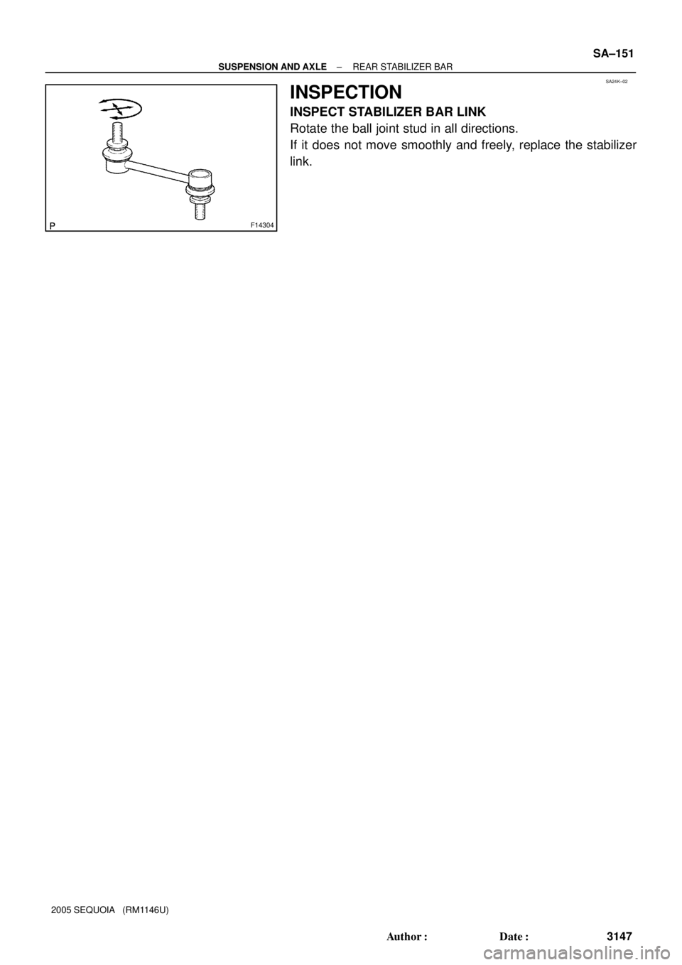
INSPECT STABILIZER BAR LINK
Rotate the ball joint stud in all directions.
If it does not move smoothly and freely, replace the stabilizer
link.
Page 3237 of 4323

TROUBLESHOOTING
PROBLEM SYMPTOMS TABLE
Use the table below to help you find the cause of the problem. The numbe")
SR01T±07
SR±2
± STEERINGTROUBLESHOOTING
3229 Author�: Date�:
2005 SEQUOIA (RM1146U)
TROUBLESHOOTING
PROBLEM SYMPTOMS TABLE
Use the table below to help you find the cause of the problem. The numbers indicate the priority of the likely
cause of the problem. Check each part in the order shown. If necessary, repair or replace these parts.
SymptomSuspect AreaSee page
Hard steering
1. Tires (Improperly inflated)
2. Power steering fluid level (Low)
3. Drive belt (Loose)
4. Front wheel alignment (Incorrect)
5. Steering system joints (Worn)
6. Suspension arm ball joints (Worn)
7. Steering column (Binding)
8. Power steering vane pump
9. Power steering gearSA±3
SR±5
SR±3
SA±4
±
SA±86
±
SR±26
SR±37
Poor return
1. Tires (Improperly inflated)
2. Front wheel alignment (Incorrect)
3. Steering column (Binding)
4. Power steering gearSA±3
SA±4
±
SR±37
Excessive play
1. Steering system joints (Worn)
2. Suspension arm ball joints (Worn)
3. Intermediate shaft, Sliding yoke (Worn)
4. Front wheel bearing (Worn)
5. Power steering gear±
SA±86
±
SA±21
SR±37
Abnormal noise
1. Power steering fluid level (Low)
2. Steering system joints (Worn)
3. Power steering vane pump
4. Power steering gearSR±5
±
SR±26
SR±37