Page 3084 of 4323

INSTALLATION
1. INSTALL LOWER SUSPENSION ARM TO")
SA23Y±05
R13282
MatchmarksMatchmarks
F07278
AC
B SA±80
± SUSPENSION AND AXLEFRONT LOWER SUSPENSION ARM
3076 Author�: Date�:
2005 SEQUOIA (RM1146U)
INSTALLATION
1. INSTALL LOWER SUSPENSION ARM TO CHASSIS
FRAME
Install the lower suspension arm with the 2 cams, bolts and cam
plates while slightly shifting the power steering gear rearward.
Torque: 130 N´m (1,325 kgf´cm, 96 ft´lbf)
NOTICE:
Do not damage the power steering gear tubes.
HINT:
After stabilizing the suspension, align the matchmarks on the
front and rear cam plates and chassis frame, and torque the
bolts.
2. CONNECT LOWER BALL JOINT TO LOWER SUSPEN-
SION ARM
Connect the lower ball joint and install the nut and a new cotter
pin.
Torque: 159 N´m (1,621 kgf´cm, 117 ft´lbf)
If the holes for the cotter pin are not aligned, tighten the nut fur-
ther up to 60°.
3. CONNECT SHOCK ABSORBER TO LOWER SUSPEN-
SION ARM
Torque: 135 N´m (1,400 kgf´cm, 100 ft´lbf)
4. CONNECT STABILIZER BAR LINK TO LOWER SUS-
PENSION ARM
Torque: 69 N´m (700 kgf´cm, 51 ft´lbf)
HINT:
If the ball joint turns together with the nut, use a hexagon (6 mm)
wrench to hold the stud.
5. INSTALL POWER STEERING GEAR
Torque:
A bolt: 165 N´m (1,700 kgf´cm, 122 ft´lbf)
B nut: 130 N´m (1,350 kgf´cm, 96 ft´lbf)
C bolt and nut: 165 N´m (1,700 kgf´cm, 122 ft´lbf)
6. CONNECT RH AND LH TIE ROD ENDS
Connect the RH and LH tie rod ends to the lower ball joints with
the nuts and new cotter pins.
Torque: 91 N´m (930 kgf´cm, 67 ft´lbf)
If the holes for the cotter pin are not aligned, tighten the nut fur-
ther up to 60°.
7. INSTALL RH AND LH FRONT WHEELS
Torque: 110 N´m (1,150 kgf´cm, 83 ft´lbf)
8. CHECK FRONT WHEEL ALIGNMENT (See page
SA±4)
9. PERFORM ZERO POINT CALIBRATION OF STEER-
ING ANGLE, MASTER CYLINDER PRESSURE, YAW
RATE AND DECELERATION SENSORS (See page
DI±897)
Page 3085 of 4323
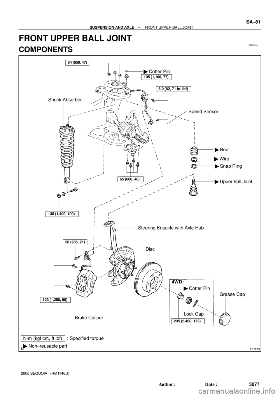
SA23Z±04
F07279
N´m (kgf´cm, ft´lbf) : Specified torque
� Non±reusable part� Boot
� Wire
� Snap Ring
� Upper Ball Joint
64 (650, 47)
Brake Caliper� Cotter Pin
105 (1,100, 77)
Shock Absorber
123 (1,250, 90)
28 (285, 21)
Steering Knuckle with Axle Hub
Disc
4WD:
� Cotter Pin
235 (2,400, 173)
Lock Cap
Grease Cap
8.0 (82, 71 in.´lbf)
Speed Sensor
135 (1,400, 100)
65 (660, 48)
± SUSPENSION AND AXLEFRONT UPPER BALL JOINT
SA±81
3077 Author�: Date�:
2005 SEQUOIA (RM1146U)
FRONT UPPER BALL JOINT
COMPONENTS
Page 3086 of 4323
SA240±03
R12864
SST
Deep Socket
Wrench SA±82
± SUSPENSION AND AXLEFRONT UPPER BALL JOINT
3078 Author�: Date�:
2005 SEQUOIA (RM1146U)
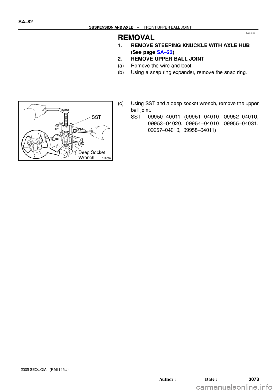
REMOVAL
1. REMOVE STEERING KNUCKLE WITH AXLE HUB
(See page SA±22)
2. REMOVE UPPER BALL JOINT
(a) Remove the wire and boot.
(b) Using a snap ring expander, remove the snap ring.
(c) Using SST and a deep socket wrench, remove the upper
ball joint.
SST 09950±40011 (09951±04010, 09952±04010,
09953±04020, 09954±04010, 09955±04031,
09957±04010, 09958±04011)
Page 3087 of 4323
SA241±03
R12776
± SUSPENSION AND AXLEFRONT UPPER BALL JOINT
SA±83
3079 Author�: Date�:
2005 SEQUOIA (RM1146U)
INSPECTION
1. INSPECT UPPER BALL JOINT BOOT FOR DAMAGE
2. INSPECT UPPER BALL JOINT FOR ROTATION
CONDITION
(a) As shown in the illustration, flip the ball joint stud back and
forth 5 times before installing the nut.
(b) Using a torque wrench, turn the nut continuously 1 turn
per 2 ± 4 seconds and take the torque reading on the 5th
turn.
Turning torque:
0.7 ± 4.4 N´m (7 ± 45 kgf´cm, 6 ± 39 in.´lbf)
Page 3088 of 4323
SA242±03
R13198
SST
Socket
Wrench SA±84
± SUSPENSION AND AXLEFRONT UPPER BALL JOINT
3080 Author�: Date�:
2005 SEQUOIA (RM1146U)
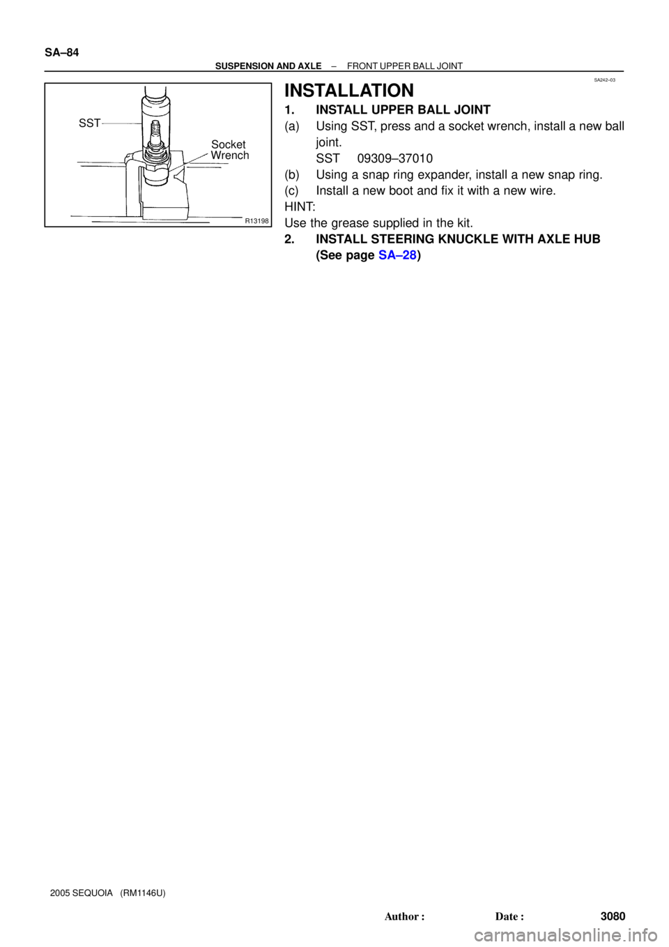
INSTALLATION
1. INSTALL UPPER BALL JOINT
(a) Using SST, press and a socket wrench, install a new ball
joint.
SST 09309±37010
(b) Using a snap ring expander, install a new snap ring.
(c) Install a new boot and fix it with a new wire.
HINT:
Use the grease supplied in the kit.
2. INSTALL STEERING KNUCKLE WITH AXLE HUB
(See page SA±28)
Page 3089 of 4323
SA243±03
W03080
± SUSPENSION AND AXLEFRONT LOWER BALL JOINT
SA±85
3081 Author�: Date�:
2005 SEQUOIA (RM1146U)
FRONT LOWER BALL JOINT
ON±VEHICLE INSPECTION
INSPECT LOWER BALL JOINT EXCESSIVE PLAY ON±VE-
HICLE
(a) Remove the front wheel and install the hub nuts to the
disc.
(b) Using a dial indicator, check the lower ball joint for exces-
sive play when you push the hub nuts up and down with
a force of 294 N (30 kgf, 66 lbf).
Maximum: 0.5 mm (0.020 in.)
Page 3090 of 4323
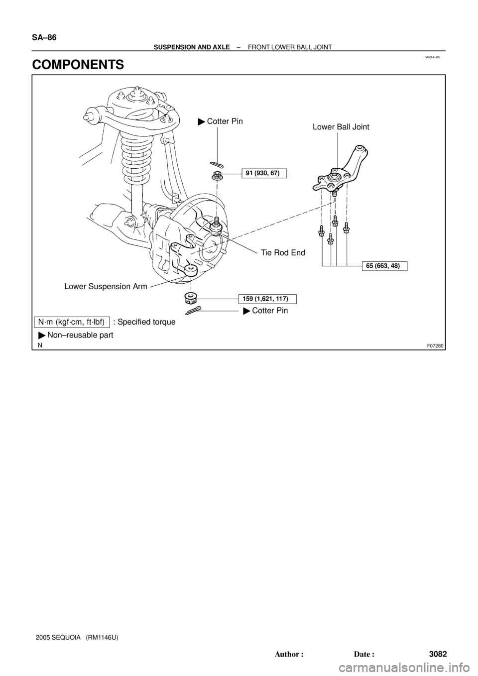
SA244±06
F07280
N´m (kgf´cm, ft´lbf) : Specified torque
� Non±reusable part
Tie Rod End
� Cotter Pin Lower Suspension ArmLower Ball Joint � Cotter Pin
91 (930, 67)
65 (663, 48)
159 (1,621, 117)
SA±86
± SUSPENSION AND AXLEFRONT LOWER BALL JOINT
3082 Author�: Date�:
2005 SEQUOIA (RM1146U)
COMPONENTS
Page 3091 of 4323
SA245±05
R13300
R13425
SST
R12863
SST
± SUSPENSION AND AXLEFRONT LOWER BALL JOINT
SA±87
3083 Author�: Date�:
2005 SEQUOIA (RM1146U)
REMOVAL
1. REMOVE FRONT WHEEL
2. LOOSEN 4 LOWER BALL JOINT SET BOLTS
HINT:
Do not remove the bolts.
3. DISCONNECT TIE ROD END
(a) Remove the cotter pin and nut from the tie rod end.
(b) Using SST, disconnect the tie rod end from the lower ball
joint.
SST 09610±20012
4. REMOVE LOWER BALL JOINT
(a) Remove the cotter pin and nut from the lower ball joint.
(b) Using SST, disconnect the lower ball joint from the lower
suspension arm.
SST 09628±62011
(c) Remove the 4 lower ball joint set bolts.
(d) While lifting the upper suspension arm and steering
knuckle, remove the lower ball joint.
(e) Support the upper suspension arm and steering knuckle
securely.