Page 2626 of 4323

16. REMOVE WATER INLET AND INLET HOUSING AS")
A23332
Front Water Bypass Joint
A23333
Rear Water Bypass Joint
A05564
± ENGINE MECHANICALCYLINDER HEAD
EM±39
2618 Author�: Date�:
2005 SEQUOIA (RM1146U)
16. REMOVE WATER INLET AND INLET HOUSING AS-
SEMBLY (See page CO±6)
17. REMOVE AIR PUMP ASSEMBLY (See page EC±22)
18. REMOVE NO.2 AIR SWITCHING VALVES
(See page EC±22)
19. REMOVE FRONT WATER BYPASS JOINT
Remove the 4 nuts, water bypass joint and 2 gaskets.
20. REMOVE REAR WATER BYPASS JOINT
Remove the 4 nuts, water bypass joint and 2 gaskets.
21. REMOVE ENGINE HANGERS
22. REMOVE CYLINDER HEAD COVERS
Remove the 18 bolts, seal washers, RH and LH cylinder head
covers and 2 gaskets.
23. IF NECESSARY, REMOVE SEMI±CIRCULAR PLUGS
AND CAMSHAFT HOUSING PLUGS
24. REMOVE CAMSHAFTS
NOTICE:
Since the thrust clearance of the camshaft is small, the
camshaft must be kept level while it is being removed. If the
camshaft is not kept level, the portion of the cylinder head
receiving the shaft thrust may crack or be damaged, caus-
ing the camshaft to seize or break. To avoid this, the follow-
ing steps should be carried out.
Page 2658 of 4323

(c) Install the")
A04015
Wire
Clamp
Bracket
A23333
Rear Water Bypass Joint
A23332
Front Water Bypass Joint
A23331
± ENGINE MECHANICALCYLINDER HEAD
EM±71
2650 Author�: Date�:
2005 SEQUOIA (RM1146U)
(c) Install the gasket to the cylinder head cover.
(d) Install the seal washer to the bolt.
(e) Install the cylinder head cover with the 9 bolts. Uniformly
tighten the bolts in several steps. Install the 2 cylinder
head covers.
Torque: 6.0 N´m (60 kgf´cm, 53 in.´lbf)
(f) Install the wire clamp bracket on the engine wire to the
camshaft bearing cap.
14. INSTALL ENGINE HANGERS
Torque: 37 N´m (380 kgf´cm, 27 ft´lbf)
15. INSTALL VVT SENSORS (See page SF±77)
16. INSTALL OIL DIPSTICK AND GUIDE FOR ENGINE
17. INSTALL OIL DIPSTICK AND GUIDE FOR A/T
18. INSTALL IGNITION COILS (See page IG±6)
19. INSTALL REAR WATER BYPASS JOINT
(a) Install 2 new gaskets to the cylinder head.
(b) Install the the water bypass joint with the 4 nuts to the cyl-
inder heads. Alternately tighten the nuts.
Torque: 18 N´m (185 kgf´cm, 13 ft´lbf)
20. INSTALL NO.2 AIR SWITCHING VALVES
(See page EC±26)
21. INSTALL AIR PUMP ASSEMBLY (See page EC±26)
22. INSTALL FRONT WATER BYPASS JOINT
Install 2 new gaskets and the water bypass joint with the 4 nuts.
Alternately tighten the nuts.
Torque: 18 N´m (185 kgf´cm, 13 ft´lbf)
23. INSTALL WATER INLET AND INLET HOUSING AS-
SEMBLY (See page CO±8)
24. ASSEMBLE INTAKE MANIFOLDS
(a) Install the 2 delivery pipes and 8 injectors (see page
SF±31).
(b) Install 2 new gaskets and fuel pulsation damper.
(c) Install a new O±ing and fuel pressure regulator with the
2 bolts.
(d) Install the fuel return pipe to the intake manifold with the
3 bolts.
(e) Connect the fuel return hose to the fuel pressure regula-
tor.
Page 2738 of 4323

REMOVAL
1. REMOVE THROTTLE BODY COVER
2. REMOVE INTA")
EC0O0±01
B17520
B17521
B17522
B17523
B17524
EC±22
± EMISSION CONTROLSECONDARY AIR INJECTION SYSTEM
2730 Author�: Date�:
2005 SEQUOIA (RM1146U)
REMOVAL
1. REMOVE THROTTLE BODY COVER
2. REMOVE INTAKE MANIFOLD (See page EM±36)
3. REMOVE VSV FOR AIR INJECTION SYSTEM
(a) Remove the 2 bolts and 2 VSVs from the intake manifold.
(b) Remove the 2 vacuum hoses from the 2 VSVs.
4. REMOVE AIR PUMP ASSEMBLY
(a) Disconnect the air hose No.2 from the air switching valve.
(b) Disconnect the air switching valve connector.
(c) Disconnect the pressure sensor connector for the air in-
jection system.
(d) Remove the 4 bolts and air pump assembly.
5. REMOVE NO. 2 AIR SWITCHING VALVE
(a) Remove the 4 nuts and 2 gaskets, and disconnect the 2
No.3 air tubes from the exhaust manifolds.
(b) Remove the 4 bolts, 2 gaskets and the 2 No.3 air tubes
from the 2 No.2 air switching valves.
(c) Remove the 4 bolts, 2 gaskets and the 2 No.2 air switch-
ing valves from the rear water by±pass joint.
(d) Remove the 2 vacuum hoses from the No.2 air switching
valves.
6. REMOVE AIR INJECTION CONTROL DRIVER
(a) Disconnect the 2 connectors from the air injection control
driver.
(b) Remove the 2 bolts and air injection control driver from
the body.
Page 2742 of 4323

INSTALLATION
1. INSTALL AIR INJECTION CONTROL DRIVER")
EC0O4±01
B17524
B17523
B17522
B17521
B17520
EC±26
± EMISSION CONTROLSECONDARY AIR INJECTION SYSTEM
2734 Author�: Date�:
2005 SEQUOIA (RM1146U)
INSTALLATION
1. INSTALL AIR INJECTION CONTROL DRIVER
(a) Install the air injection control driver with the 2 bolts to the
body.
Torque: 18 N´m (184 kgf´cm, 13 ft´lbf)
(b) Connect the 2 connectors to the air injection control driv-
er.
2. INSTALL NO. 2 AIR SWITCHING VALVE
(a) Connect the 2 vacuum hoses to the No.2 air switching
valves.
(b) Install 2 new gaskets and 2 No.2 air switching valves with
the 4 bolts to the rear water by±pass joint.
Torque: 10 N´m (102 kgf´cm, 7 ft´lbf)
(c) Install 2 new gaskets, and connect the 2 No.3 air tubes
with the 4 bolts to the No.2 air switching valve.
Torque: 10 N´m (102 kgf´cm, 7 ft´lbf)
(d) Install the 2 new gaskets, and connect the 2 No.3 air
tubes with the 4 nuts to the exhaust manifold.
Torque: 10 N´m (102 kgf´cm, 7 ft´lbf)
3. INSTALL AIR PUMP ASSEMBLY
(a) Install the air pump assembly with the 4 bolts.
Torque: 16 N´m (163 kgf´cm, 12 ft´lbf)
(b) Connect the pressure sensor connector for the air injec-
tion system.
(c) Connect the air switching valve connector.
(d) Connect the air hose No.2 to the air switching valve.
4. INSTALL VSV FOR AIR INJECTION SYSTEM
(a) Install the 2 VSVs with the 2 bolts to the intake manifold.
Torque: 7.5 N´m (76 kgf´cm, 66 in.´lbf)
(b) Connect the 2 vacuum hoses to the 2 VSVs.
5. INSTALL INTAKE MANIFOLD (See page EM±60)
6. INSTALL THROTTLE BODY COVER
Page 2753 of 4323

REMOVAL
1. REMOVE FUEL TAN")
SF130±04
B17536Tube Joint Clip
B17537
Nylon Tube Fuel Tube Joint
O±Ring
Tube Joint Clip
B17538
SST
Rib
± SFIFUEL PUMP
SF±11
2745 Author�: Date�:
2005 SEQUOIA (RM1146U)
REMOVAL
1. REMOVE FUEL TANK ASSEMBLY (See page SF±34)
2. DISCONNECT FUEL SUCTION TUBE
Remove the 2 tube clips, and pull out the 2 fuel tubes.
NOTICE:
�Before this operation, check the connector for dirt,
mud or other contamination. Clean if necessary.
�Be careful of mud. The connector's O±ring, which
seals the pipe and connector, is easily contaminated.
�Do not use any tool in this operation.
�Do not bend or twist the nylon tube. Protect the con-
nector by covering it with a plastic bag.
�When the pipe and connector are stuck, push and pull
the connector to release and pull the connector out
carefully.
3. REMOVE FUEL PUMP ASSEMBLY
(a) Using SST, loosen the fuel pump gauge retainer.
SST 09808±14020 (09808±01410, 09808±01420,
09808±01430)
HINT:
A rib on the fuel pump gauge retainer fits into a tip of the SST.
(b) Remove the fuel pump gauge retainer.
(c) Remove the fuel suction tube.
NOTICE:
Be careful not to bend the arm of the fuel sender gauge.
(d) Remove the gasket from the fuel tank.
Page 2761 of 4323

SF1XG±01
B17551
KeywayKey
B17552
ºSº Mark
Triangle Mark
B17553
SST
Rib
ºMAX.º Mark
ºAº Mark
Triangle Mark
B17489Tube Joint Clip
± SFIFUEL PUMP
SF±19
2753 Author�: Date�:
2005 SEQUOIA (RM1146U)
INSTALLATION
1. INSTALL FUEL PUMP ASSEMBLY
(a) Install a new gasket to the fuel tank.
(b) Install the fuel pump assembly to the fuel tank.
NOTICE:
Be careful not to bend the arm of the fuel sender gauge.
(c) Align the keyway of the fuel suction tube support with the
key of the fuel suction plate No.1.
(d) Apply MP grease to the entire interior surface of the fuel
pump gauge retainer.
(e) Align the triangle mark on the new fuel pump gauge re-
tainer with the ºSº mark on the fuel tank while pushing
down the fuel suction tube. Attach the fuel pump gauge
retainer.
(f) Rotate the fuel pump gauge retainer by hand. Use an SST
to tighten the fuel pump gauge retainer by turning it one
and a half times. The triangle mark on the fuel pump
gauge retainer must be positioned between the ºAº and
ºMAX.º marks on the fuel tank.
SST 09808±14020 (09808±01410, 09808±01420,
09808±01430)
NOTICE:
Do not use other tools in this operation. Damage to the fuel
pump gauge retainer and the fuel tank may result.
HINT:
A rib on the fuel pump gauge retainer fits into a tip of the SST.
2. CONNECT FUEL SUCTION TUBE
Connect the fuel pump tube and return tube to the fuel tank with
the tube joint clips.
Page 2762 of 4323
SF±20
± SFIFUEL PUMP
2754 Author�: Date�:
2005 SEQUOIA (RM1146U)
NOTICE:
�Check that there are no scratches or foreign objects
on the connecting part.
�Check that the fuel tube joint is inserted securely.
�Check that the tube joint clip is on the collar of the fuel
tube joint.
�After installing the tube joint clip, check that the fuel
tube joint has not been pulled off.
3. CHECK FOR FUEL LEAKS
4. INSTALL FUEL TANK ASSEMBLY (See page SF±36)
Page 2830 of 4323
CO0IR±06
B17478
B17479
CO±6
± COOLINGWATER PUMP
2822 Author�: Date�:
2005 SEQUOIA (RM1146U)
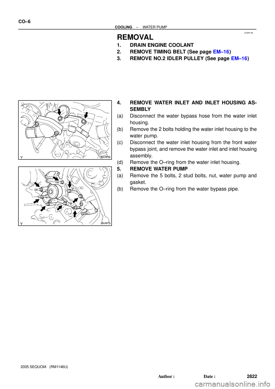
REMOVAL
1. DRAIN ENGINE COOLANT
2. REMOVE TIMING BELT (See page EM±16)
3. REMOVE NO.2 IDLER PULLEY (See page EM±16)
4. REMOVE WATER INLET AND INLET HOUSING AS-
SEMBLY
(a) Disconnect the water bypass hose from the water inlet
housing.
(b) Remove the 2 bolts holding the water inlet housing to the
water pump.
(c) Disconnect the water inlet housing from the front water
bypass joint, and remove the water inlet and inlet housing
assembly.
(d) Remove the O±ring from the water inlet housing.
5. REMOVE WATER PUMP
(a) Remove the 5 bolts, 2 stud bolts, nut, water pump and
gasket.
(b) Remove the O±ring from the water bypass pipe.