Page 3247 of 4323
SR1F3±03
F17895
Steering Wheel Pad
Steering
Wheel
Column Lower
CoverCombination
SwitchSteering Column Assembly
Transmission Control
Cable Assembly
Lower LH Finish PanelColumn Hole
Cover No. 2
No. 2 Universal
Joint Assembly
No. 2 Heater to Register Dust Torx® Screw
35 (360, 26)
35 (360, 26)
8.0 (82, 71 in.´lbf)
26 (260, 19)
26 (260, 19)
8.8 (90, 78 in.´lbf)
50 (510, 37)
8.8 (90, 78 in.´lbf)
Front Door Scuff PlateCowl Side Trim
Hood Lock
Release Lever
8.0 (82, 71 in.´lbf)
Side Panel
No. 2 Intermediate
Shaft AssemblyBrake Pedal
Return Spring
Column Upper Cover
N´m (kgf´cm, ft´lbf): Specified torque
Steering Wheel Lower
No. 3 Cover
Steering Wheel Lower
No. 2 Cover
35 (360, 26)
Sliding Yoke
Torx® Screw SR±12
± STEERINGTILT STEERING COLUMN
3239 Author�: Date�:
2005 SEQUOIA (RM1146U)
TILT STEERING COLUMN
COMPONENTS
Page 3250 of 4323

5. REMOVE COMBINATION SWITCH WITH SPIRAL
CABLE
(a) Disconnect the 4 connectors.")
F17896
A
BMatchmarks
F13260
F06703
± STEERINGTILT STEERING COLUMN
SR±15
3242 Author�: Date�:
2005 SEQUOIA (RM1146U)
5. REMOVE COMBINATION SWITCH WITH SPIRAL
CABLE
(a) Disconnect the 4 connectors.
(b) Disconnect the airbag connector.
(c) Remove the 3 screws and combination switch.
6. REMOVE SPIRAL CABLE (See page BE±26)
NOTICE:
Do not disassemble the cable or apply oil to it.
7. REMOVE COWL SIDE TRIM AND FRONT DOOR
SCUFF PLATE
8. REMOVE LOWER LH FINISH PANEL
(a) Remove the 2 screws and disconnect the hood lock re-
lease lever from the panel.
(b) Remove the 4 panel set bolts and lower LH finish panel.
9. REMOVE NO. 2 HEATER TO REGISTER DUCT
10. REMOVE BRAKE PEDAL RETURN SPRING
11. REMOVE SLIDING YOKE
(a) Put matchmarks on the sliding yoke and No. 2 intermedi-
ate shaft assembly.
(b) Remove the ºAº bolt.
(c) Remove the ºBº bolt.
(d) Slide the sliding yoke and remove it.
12. REMOVE COLUMN HOLE COVER NO. 2
Remove the 3 bolts and column hole cover No. 2.
13. DISCONNECT TRANSMISSION CONTROL CABLE
ASSEMBLY
Disconnect the cable assembly from the column shift lever as-
sembly.
14. REMOVE STEERING COLUMN ASSEMBLY WITH
NO. 2 UNIVERSAL JOINT ASSEMBLY
(a) Disconnect the connectors.
(b) Remove the 4 steering column set nuts.
(c) Pull out the steering column assembly with the No. 2 uni-
versal joint assembly connected.
Page 3251 of 4323
F17913
Matchmarks
F17897Matchmarks
SR±16
± STEERINGTILT STEERING COLUMN
3243 Author�: Date�:
2005 SEQUOIA (RM1146U)
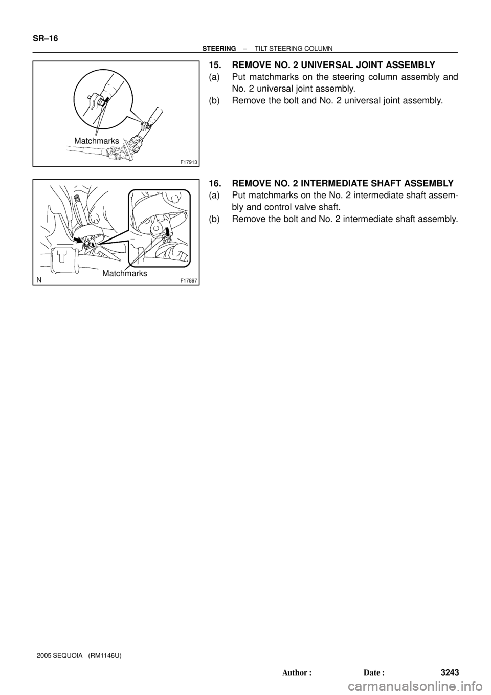
15. REMOVE NO. 2 UNIVERSAL JOINT ASSEMBLY
(a) Put matchmarks on the steering column assembly and
No. 2 universal joint assembly.
(b) Remove the bolt and No. 2 universal joint assembly.
16. REMOVE NO. 2 INTERMEDIATE SHAFT ASSEMBLY
(a) Put matchmarks on the No. 2 intermediate shaft assem-
bly and control valve shaft.
(b) Remove the bolt and No. 2 intermediate shaft assembly.
Page 3253 of 4323

9. REMOVE STEERING COLUMN HOUSING WITH MAIN")
F06734
Plate Washer A
Plate Washer BSST
Screw
R12472
SST
Retaining Ring SR±18
± STEERINGTILT STEERING COLUMN
3245 Author�: Date�:
2005 SEQUOIA (RM1146U)
9. REMOVE STEERING COLUMN HOUSING WITH MAIN
SHAFT ASSEMBLY
(a) Set SST, 2 plate washers (18 and 36 mm outer diameter)
and a screw (4.0 mm diameter, 0.7 mm pitch, 15.0 mm
length), as shown in the illustration. Then remove the 2
pivot pins.
SST 09910±00015 (09911±00011, 09912±00010)
Reference
Plate washer A (18 mm): 90562±04012
Plate washer B (36 mm): 90201±10201
Screw: 90154±40015
(b) Remove the column housing with the shaft assembly from
the column tube assembly.
NOTICE:
Do not bend the universal joint of the main shaft assembly
more than 15°.
(c) Remove the tilt spring and spring guide.
10. REMOVE 2 TILT NO. 1 STOPPERS
11. REMOVE MAIN SHAFT STOPPER
12. REMOVE MAIN SHAFT ASSEMBLY
(a) Install SST to the main shaft assembly, as shown in the
illustration.
SST 09612±07010
(b) Using SST, compress the compression spring.
SST 09612±07010
NOTICE:
Do not bend the universal joint of the shaft assembly more
than 15°.
HINT:
Hold the shaft assembly with your hand to prevent rotation.
(c) Using a screwdriver, remove the No. 2 steering column
ring.
(d) Remove the spring retainer, compression spring, upper
bearing inner race seat and inner race.
13. REMOVE TILT LEVER
Remove the tilt lever lock shaft and shift lever.
Page 3256 of 4323

REASSEMBLY
NOTICE:
When using a vise, do not overtighten it")
SR0V3±05
R12807
Washer
Retaining RingSST
F06735
F06736
± STEERINGTILT STEERING COLUMN
SR±21
3248 Author�: Date�:
2005 SEQUOIA (RM1146U)
REASSEMBLY
NOTICE:
When using a vise, do not overtighten it.
1. COAT PARTS INDICATED BY ARROWS WITH MOLYB-
DENUM DISULFIDE LITHIUM BASE GREASE (See
page SR±12)
2. INSTALL TILT LEVER
Install the tilt lever with a new tilt lever lock shaft.
Torque: 9.0 N´m (90 kgf´cm, 78 in.´lbf)
3. INSTALL MAIN SHAFT ASSEMBLY
(a) Install the inner race, upper bearing inner race seat, com-
pression spring and spring retainer.
(b) Install a new No. 2 steering column ring to the main shaft
assembly.
(c) Install the washer of SST on the main shaft assembly.
SST 09612±07010
(d) Set SST on the main shaft assembly, as shown in the il-
lustration.
SST 09612±07010
(e) Using SST, push down the retaining ring until it fits into the
shaft groove and install the main shaft assembly.
NOTICE:
Do not bend the universal joint of the shaft assembly more
than 15°.
HINT:
Hold the main shaft assembly with your hand to prevent rota-
tion.
4. INSTALL MAIN SHAFT STOPPER
5. INSTALL 2 NEW TILT NO. 1 STOPPERS
6. INSTALL STEERING COLUMN HOUSING WITH MAIN
SHAFT ASSEMBLY
(a) Install the steering column housing with the main shaft as-
sembly into the column tube assembly.
(b) Install the tilt spring and spring guide.
(c) Hold the steering column housing and steering column
housing support in a vise.
(d) Temporarily install 2 new pivot pins.
(e) Using a punch and a hammer, tap in the pivot pin.
(f) Using a pin punch and a hammer, stake at 3 places evenly
around the hole as shown in the illustration.
Page 3258 of 4323

INSTALLATION
NOTICE:
When replacing the steering angle sensor, drive t")
SR1KE±01
F17897Matchmarks
F17913
Matchmarks
± STEERINGTILT STEERING COLUMN
SR±23
3250 Author�: Date�:
2005 SEQUOIA (RM1146U)
INSTALLATION
NOTICE:
When replacing the steering angle sensor, drive the vehicle
straight ahead at a speed of 6.5 mph (10.5 km/h) or more.
Accordingly, zero point calibration of the steering angle
sensor is performed.
HINT:
If the steering angle sensor zero point calibration is not per-
formed, its value will be fixed. Check after driving the vehicle
straight ahead at a speed of 6.5 mph (10.5 km/h) or more (See
page DI±946).
1. INSTALL NO. 2 INTERMEDIATE SHAFT ASSEMBLY
(a) Align the matchmark on the No. 2 intermediate shaft as-
sembly with the one on the control valve shaft.
(b) Install the bolt.
Torque: 35 N´m (360 kgf´cm, 26 ft´lbf)
2. CONNECT NO. 2 UNIVERSAL JOINT ASSEMBLY
(a) Align the matchmark on the column assembly with the
one on the No. 2 universal joint assembly.
(b) Install the bolt.
Torque: 35 N´m (360 kgf´cm, 26 ft´lbf)
3. INSTALL STEERING COLUMN ASSEMBLY WITH NO.
2 UNIVERSAL JOINT ASSEMBLY
(a) Install the column assembly with the No. 2 universal joint
assembly.
(b) Install the 4 steering column set nuts.
Torque: 26 N´m (260 kgf´cm, 19 ft´lbf)
NOTICE:
Take care not to rotate the steering shaft.
(c) Connect the connectors.
4. CONNECT TRANSMISSION CONTROL CABLE AS-
SEMBLY
Connect the cable assembly to the shift lever assembly.
Page 3294 of 4323

OPERATION
CAUTION:
Be sure to perform the initialization of th")
RS116±01
H24695
H23918Spiral Cable
H16182
± SUPPLEMENTAL RESTRAINT SYSTEMSRS AIRBAG
RS±3
3286 Author�: Date�:
2005 SEQUOIA (RM1146U)
OPERATION
CAUTION:
Be sure to perform the initialization of the occupant classi-
fication ECU if any of the following conditions occur (see
page DI±1128). If the initialization is not performed, the SRS
may not operate properly.
�The occupant classification ECU is replaced.
�Accessories (seatback tray, seat cover, etc.) are
installed to the vehicle.
�The passenger seat is removed from the vehicle, and
then reinstalled or replaced.
�The passenger airbag ON/OFF indicator light (ºOFFº)
comes on when the passenger seat is not occupied.
�The vehicle is brought to the workshop for repair due
to an accident or collision.
1. STEERING WHEEL PAD
The inflator and bag of the SRS are stored in the steering wheel
pad and cannot be disassembled. The inflator contains a squib,
igniter charge, and gas generator, etc., and inflates the bag
when instructed by the airbag sensor assembly. The steering
wheel pad cannot be disassembled.
2. SPIRAL CABLE
A spiral cable is used as an electrical joint from the vehicle body
side to the steering wheel. The spiral cable cannot be disas-
sembled.
3. FRONT PASSENGER AIRBAG ASSEMBLY
The inflator and bag of the SRS are stored in the front passen-
ger airbag assembly and cannot be disassembled. The inflator
contains a squib, igniter charge, gas generator, etc., and in-
flates the bag when instructed by the airbag sensor assembly.
The front passenger airbag assembly cannot be disassembled.
Page 3734 of 4323
BO47V±04
H16752
Center Leg Cover
Front Leg
Front Leg CushionNo. 1 Roof Inner Rack
Bracket Center SupportRoof Inner Rack Retainer
Weatherstrip
Front Leg Cover
Front Leg
Front Leg Cushion Front Leg CoverRear Leg CoverFront StayRoof Rack Bar Joint
Center Support
Sub±assemblyRoof Inner
Rack Retainer
Rear Leg Cover
Rear Leg
Rear Leg Cover
Center Leg Cover
Rear Leg
Rear Leg Cushion
11 (115, 8)
N´m (kgf´cm, ft´lbf) : Specified torque
11 (115, 8)
11 (115, 8)
11 (115, 8)
11 (115, 8)
11 (115, 8)
± BODYROOF RACK
BO±173
3726 Author�: Date�:
2005 SEQUOIA (RM1146U)
ROOF RACK
COMPONENTS