Page 3040 of 4323

INSTALLATION
1. INSTALL DRIVE SHAFT TO DIFFERENTIAL
(a) Install a new snap ring to the inboard jo")
SA14I±10
SA±36
± SUSPENSION AND AXLEFRONT DRIVE SHAFT
3032 Author�: Date�:
2005 SEQUOIA (RM1146U)
INSTALLATION
1. INSTALL DRIVE SHAFT TO DIFFERENTIAL
(a) Install a new snap ring to the inboard joint shaft.
(b) Apply gear oil to the inboard joint shaft and differential case sliding surface.
(c) Set the snap ring with opening side facing downward.
(d) Using a brass bar and hammer, install the drive shaft.
NOTICE:
Be careful not to damage the dust cover and oil seal.
HINT:
Whether the inboard joint shaft is in contact with the pinion shaft or not can be known from the sound or feel-
ing when driving.
(e) Check that there is 2 ± 3 mm (0.08 ± 0.12 in.) of play in the axial direction.
(f) Check that the drive shaft cannot be removed by hand.
2. LH drive shaft:
INSTALL LH SHOCK ABSORBER (See page SA±70)
3. CONNECT DRIVE SHAFT TO STEERING KNUCKLE
NOTICE:
Be careful not to damage the oil seal, boots and dust seal.
4. CONNECT LOWER SUSPENSION ARM TO LOWER BALL JOINT
(a) Connect the lower suspension arm to the lower ball joint.
(b) Install the nut and a new cotter pin.
If the holes for the cotter pin are not aligned, tighten the nut further up to 60°.
HINT:
Face the hole for the cotter pin forward.
Torque: 140 N´m (1,450 kgf´cm, 103 ft´lbf)
5. INSTALL DRIVE SHAFT LOCK NUT
(a) While applying brakes, install the nut.
Torque: 235 N´m (2,400 kgf´cm, 173 ft´lbf)
(b) Install the lock cap and a new cotter pin.
If the holes for the cotter pin are not aligned, tighten the nut further up to 60°.
6. FILL DIFFERENTIAL WITH HYPOID GEAR OIL (See page SA±38)
7. INSTALL ENGINE UNDER COVER
8. INSTALL FRONT WHEEL
Torque: 110 N´m (1,150 kgf´cm, 83 ft´lbf)
Page 3075 of 4323
SA183±05
F07268
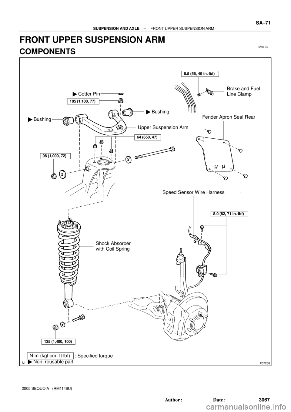
Upper Suspension Arm
N´m (kgf´cm, ft´lbf)
: Specified torque
� Non±reusable part
Brake and Fuel
Line Clamp
Fender Apron Seal Rear
Speed Sensor Wire Harness � Bushing
� Bushing � Cotter Pin
105 (1,100, 77)
64 (650, 47)
98 (1,000, 72)
135 (1,400, 100)
Shock Absorber
with Coil Spring
8.0 (82, 71 in.´lbf)
5.5 (56, 49 in.´lbf)
± SUSPENSION AND AXLEFRONT UPPER SUSPENSION ARM
SA±71
3067 Author�: Date�:
2005 SEQUOIA (RM1146U)
FRONT UPPER SUSPENSION ARM
COMPONENTS
Page 3076 of 4323
SA23W±03
R13196
SST
F07269
F07270
SA±72
± SUSPENSION AND AXLEFRONT UPPER SUSPENSION ARM
3068 Author�: Date�:
2005 SEQUOIA (RM1146U)
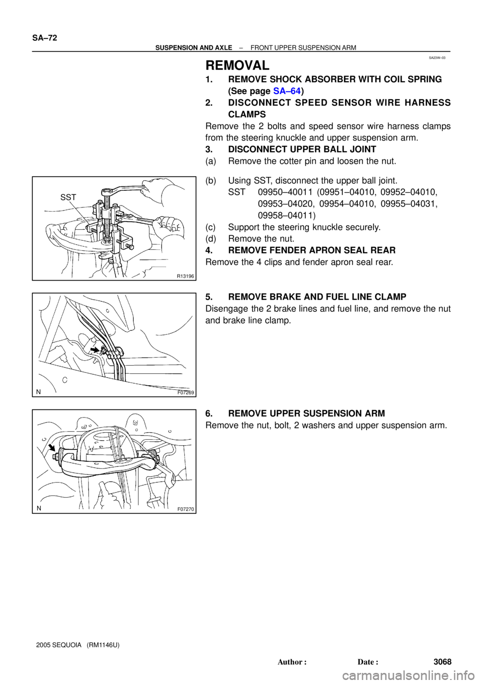
REMOVAL
1. REMOVE SHOCK ABSORBER WITH COIL SPRING
(See page SA±64)
2. DISCONNECT SPEED SENSOR WIRE HARNESS
CLAMPS
Remove the 2 bolts and speed sensor wire harness clamps
from the steering knuckle and upper suspension arm.
3. DISCONNECT UPPER BALL JOINT
(a) Remove the cotter pin and loosen the nut.
(b) Using SST, disconnect the upper ball joint.
SST 09950±40011 (09951±04010, 09952±04010,
09953±04020, 09954±04010, 09955±04031,
09958±04011)
(c) Support the steering knuckle securely.
(d) Remove the nut.
4. REMOVE FENDER APRON SEAL REAR
Remove the 4 clips and fender apron seal rear.
5. REMOVE BRAKE AND FUEL LINE CLAMP
Disengage the 2 brake lines and fuel line, and remove the nut
and brake line clamp.
6. REMOVE UPPER SUSPENSION ARM
Remove the nut, bolt, 2 washers and upper suspension arm.
Page 3078 of 4323

INSTALLATION
1. INSTALL UPPER SUSPENSION ARM
Install the upper suspension arm with the 2")
SA187±06
SA±74
± SUSPENSION AND AXLEFRONT UPPER SUSPENSION ARM
3070 Author�: Date�:
2005 SEQUOIA (RM1146U)
INSTALLATION
1. INSTALL UPPER SUSPENSION ARM
Install the upper suspension arm with the 2 washers, bolt and nut.
Torque: 98 N´m (1,000 kgf´cm, 72 ft´lbf)
HINT:
After stabilizing the suspension, torque the nut.
2. INSTALL BRAKE AND FUEL LINE CLAMP
Torque: 5.5 N´m (56 kgf´cm, 49 in.´lbf)
3. INSTALL FENDER APRON SEAL REAR
4. CONNECT UPPER BALL JOINT
(a) Connect the upper ball joint to the upper suspension arm.
(b) Install the nut and a new cotter pin.
If the holes for the cotter pin are not aligned, tighten the nut further up to 60°.
Torque: 105 N´m (1,100 kgf´cm, 77 ft´lbf)
5. CONNECT SPEED SENSOR WIRE HARNESS CLAMPS
Torque: 8.0 N´m (82 kgf´cm, 71 in.´lbf)
6. INSTALL SHOCK ABSORBER WITH COIL SPRING (See page SA±70)
7. CHECK FRONT WHEEL ALIGNMENT (See page SA±4)
8. PERFORM ZERO POINT CALIBRATION OF STEERING ANGLE, MASTER CYLINDER PRES-
SURE, YAW RATE AND DECELERATION SENSORS (See page DI±897)
Page 3085 of 4323
SA23Z±04
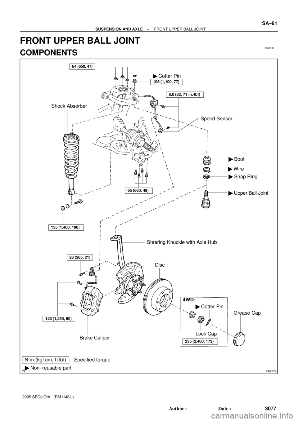
F07279
N´m (kgf´cm, ft´lbf) : Specified torque
� Non±reusable part� Boot
� Wire
� Snap Ring
� Upper Ball Joint
64 (650, 47)
Brake Caliper� Cotter Pin
105 (1,100, 77)
Shock Absorber
123 (1,250, 90)
28 (285, 21)
Steering Knuckle with Axle Hub
Disc
4WD:
� Cotter Pin
235 (2,400, 173)
Lock Cap
Grease Cap
8.0 (82, 71 in.´lbf)
Speed Sensor
135 (1,400, 100)
65 (660, 48)
± SUSPENSION AND AXLEFRONT UPPER BALL JOINT
SA±81
3077 Author�: Date�:
2005 SEQUOIA (RM1146U)
FRONT UPPER BALL JOINT
COMPONENTS
Page 3098 of 4323
SA17R±04
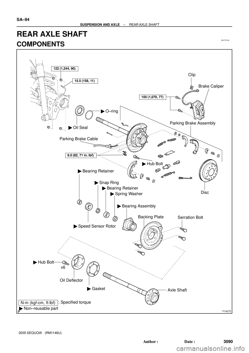
F14272
122 (1,244, 90)
� Oil Seal
� O±ring
Parking Brake Assembly
Disc Brake Caliper
� Bearing Retainer
� Speed Sensor Rotor
� Snap Ring
� Bearing Retainer
� Spring Washer
Backing PlateSerration Bolt
� Hub Bolt
Oil Deflector
� GasketAxle Shaft
N´m (kgf´cm, ft´lbf): Specified torque
� Non±reusable partx6
105 (1,070, 77)
15.5 (158, 11)
Clip
Parking Brake Cable
� Hub Bolt
8.0 (82, 71 in.´lbf)
� Bearing Assembly SA±94
± SUSPENSION AND AXLEREAR AXLE SHAFT
3090 Author�: Date�:
2005 SEQUOIA (RM1146U)
REAR AXLE SHAFT
COMPONENTS
Page 3099 of 4323

REMOVAL
1. REMOVE REAR WHEEL
Torque: 110 N´m (1,150 kgf´cm, 83 ft´lbf)")
SA17S±04
F14273
SST
F14274
F14275
± SUSPENSION AND AXLEREAR AXLE SHAFT
SA±95
3091 Author�: Date�:
2005 SEQUOIA (RM1146U)
REMOVAL
1. REMOVE REAR WHEEL
Torque: 110 N´m (1,150 kgf´cm, 83 ft´lbf)
2. DISCONNECT BRAKE LINE
Using SST, disconnect the brake line and remove the clip.
SST 09023±00101
Torque: 15.5 N´m (158 kgf´cm, 11 ft´lbf)
3. REMOVE BRAKE CALIPER AND DISC
Remove the 2 bolts, brake caliper and disc.
Torque: 105 N´m (1,070 kgf´cm, 77 ft´lbf)
4. CHECK BEARING BACKLASH AND AXLE SHAFT
DEVIATION
(a) Using a dial indicator, check the backlash in the bearing
shaft direction.
Maximum: 0.6 mm (0.024 in.)
If the backlash exceeds the maximum, replace the bearing.
(b) Using a dial indicator, check the deviation at the surface
of the axle shaft outside the hub bolt.
Maximum: 0.1 mm (0.0040 in.)
If the deviation exceeds the maximum, replace the axle shaft.
5. REMOVE PARKING BRAKE ASSEMBLY
(a) Remove the parking brake assembly (See page
BR±43).
(b) Remove the 2 bolts and pull out the parking brake cable
from the backing plate.
Torque: 8.0 N´m (82 kgf´cm, 71 in.´lbf)
(c) Use the same procedures described above to the other
side.
Page 3106 of 4323
SA17X±07
SA±102
± SUSPENSION AND AXLEREAR AXLE SHAFT
3098 Author�: Date�:
2005 SEQUOIA (RM1146U)
INSTALLATION
Installation is in the reverse order of removal (See page SA±95).
HINT:
After installation, fill the brake reservoir with brake fluid, bleed the brake system (See page BR±4), check
for leaks and check the speed sensor signal (See page DI±899).