Page 2667 of 4323

A09151
A08905
A08907
EM±80
± ENGINE MECHANICALENGINE UNIT (2WD)
2659 Author�: Date�:
2005 SEQUOIA (RM1146U)
(d) Disconnect the hose clamp for the PS air hose.
(e) Disconnect the PS air hose from the upper intake man-
ifold.
(f) Disconnect the 2 heater hoses.
(g) Disconnect the ground strap from the cowl panel.
(h) Disconnect the fuel inlet hose and clamps.
(i) Disconnect the fuel return hose and clamp.
(j) Disconnect the air inlet hose from the charcoal canister.
(k) Disconnect the EVAP hose from the charcoal canister.
(l) w/o Hydraulic brake booster:
Disconnect the brake booster tube.
11. REMOVE FRONT EXHAUST PIPES
(See page EM±126)
12. REMOVE PROPELLER SHAFT (See page PR±3)
13. REMOVE FRONT STABILIZER BAR
(See page SA±91)
14. DISCONNECT POWER STEERING GEAR PIPES
Disconnect the pressure feed tube, turn tube and pressure
tubes from the PS gear assembly.
(See page SR±40, SR±41)
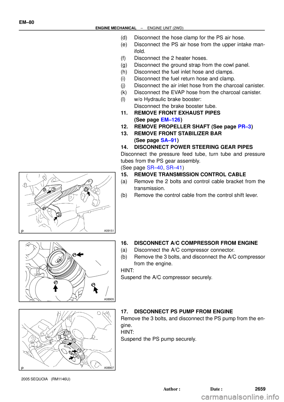
15. REMOVE TRANSMISSION CONTROL CABLE
(a) Remove the 2 bolts and control cable bracket from the
transmission.
(b) Remove the control cable from the control shift lever.
16. DISCONNECT A/C COMPRESSOR FROM ENGINE
(a) Disconnect the A/C compressor connector.
(b) Remove the 3 bolts, and disconnect the A/C compressor
from the engine.
HINT:
Suspend the A/C compressor securely.
17. DISCONNECT PS PUMP FROM ENGINE
Remove the 3 bolts, and disconnect the PS pump from the en-
gine.
HINT:
Suspend the PS pump securely.
Page 2673 of 4323

A08905
A09151
(a) EM±86
± ENGINE MECHANICALENGINE UNIT (2WD)
2665 Author�: Date�:
2005 SEQUOIA (RM1146U)
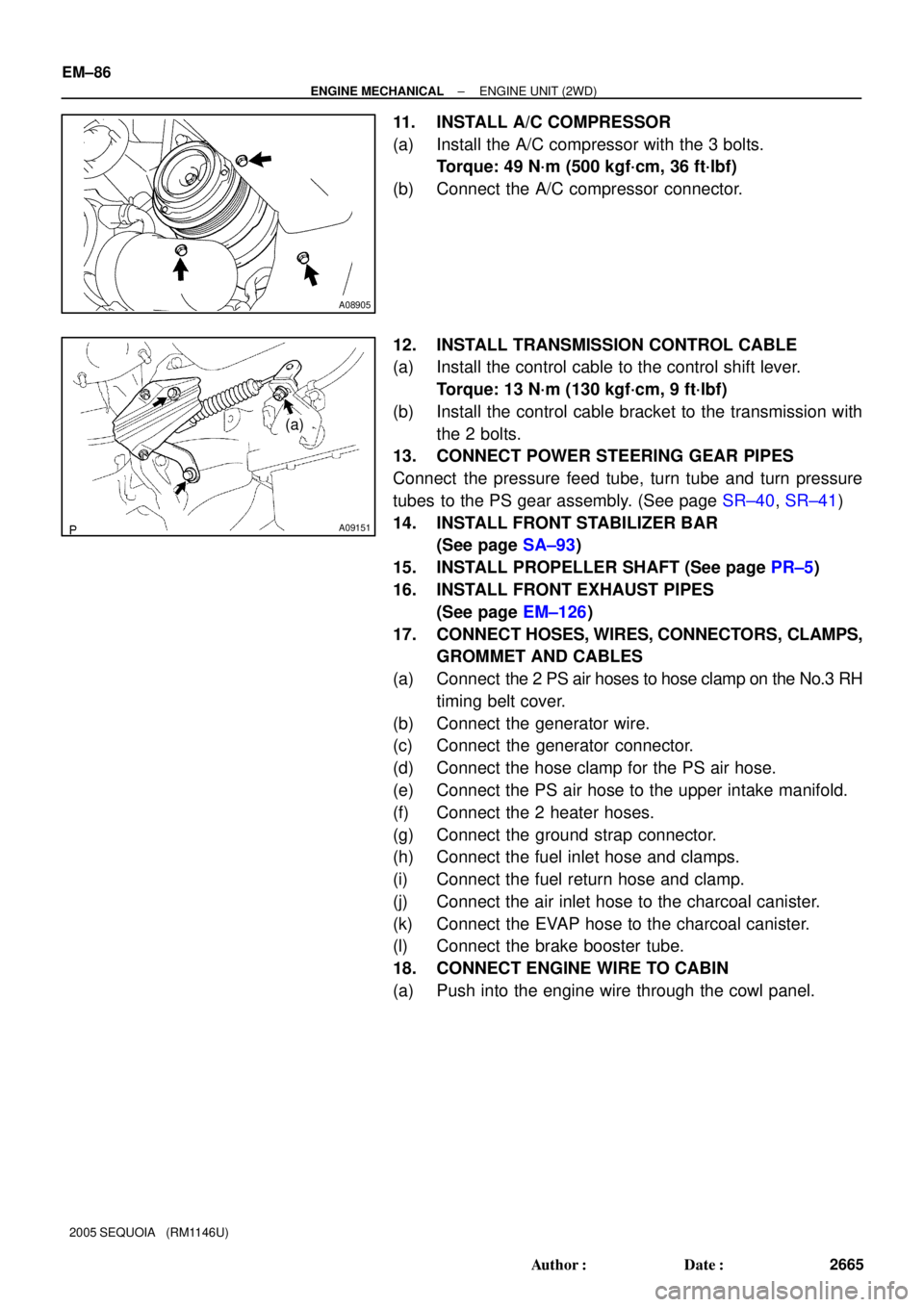
11. INSTALL A/C COMPRESSOR
(a) Install the A/C compressor with the 3 bolts.
Torque: 49 N´m (500 kgf´cm, 36 ft´lbf)
(b) Connect the A/C compressor connector.
12. INSTALL TRANSMISSION CONTROL CABLE
(a) Install the control cable to the control shift lever.
Torque: 13 N´m (130 kgf´cm, 9 ft´lbf)
(b) Install the control cable bracket to the transmission with
the 2 bolts.
13. CONNECT POWER STEERING GEAR PIPES
Connect the pressure feed tube, turn tube and turn pressure
tubes to the PS gear assembly. (See page SR±40, SR±41)
14. INSTALL FRONT STABILIZER BAR
(See page SA±93)
15. INSTALL PROPELLER SHAFT (See page PR±5)
16. INSTALL FRONT EXHAUST PIPES
(See page EM±126)
17. CONNECT HOSES, WIRES, CONNECTORS, CLAMPS,
GROMMET AND CABLES
(a) Connect the 2 PS air hoses to hose clamp on the No.3 RH
timing belt cover.
(b) Connect the generator wire.
(c) Connect the generator connector.
(d) Connect the hose clamp for the PS air hose.
(e) Connect the PS air hose to the upper intake manifold.
(f) Connect the 2 heater hoses.
(g) Connect the ground strap connector.
(h) Connect the fuel inlet hose and clamps.
(i) Connect the fuel return hose and clamp.
(j) Connect the air inlet hose to the charcoal canister.
(k) Connect the EVAP hose to the charcoal canister.
(l) Connect the brake booster tube.
18. CONNECT ENGINE WIRE TO CABIN
(a) Push into the engine wire through the cowl panel.
Page 2676 of 4323
A08928
ECM Connector ECM and Bracket AssemblyHeater to Register Dust
Lower No.2 Finish Panel
Glove Compartment Door
Wire Harness Connector (Cassette Connector)
A23366
Engine Wire Clamp
Engine WireHeater Hose Ground Strap
Fuel Inlet
HoseBattery
Negative
(±) Cable Heater Hose
Fuel Return
Hose
Generator Wire
Battery
Positive (+)
Terminal Clamp
Generator
Connector
EVAP Hose
w/o Hydraulic Brake Booster:
Brake Booster Tube
± ENGINE MECHANICALENGINE UNIT (4WD)
EM±89
2668 Author�: Date�:
2005 SEQUOIA (RM1146U)
Page 2680 of 4323

B07536
Disconnect
A08905
A08907
A08936
± ENGINE MECHANICALENGINE UNIT (4WD)
EM±93
2672 Author�: Date�:
2005 SEQUOIA (RM1146U)
(f) Disconnect the engine wire from the engine wire bracket
and remove the 2 nuts, bolt and bracket.
(g) Pull out the engine wire from the cowl panel.
14. DISCONNECT HOSES, WIRES, CONNECTORS,
CLAMPS, GROMMET AND CABLES
(a) Disconnect the 2 PS air hoses from hose clamp on the
No.3 RH timing belt cover.
(b) Disconnect the generator wire.
(c) Disconnect the generator connector.
(d) Disconnect the hose clamp for the PS air hose.
(e) Disconnect the PS air hose from the upper intake man-
ifold.
(f) Disconnect the 2 heater hoses.
(g) Disconnect the ground strap from the cowl panel.
(h) Disconnect the fuel inlet hose and clamps.
(i) Disconnect the fuel return hose and clamp.
(j) Disconnect the air inlet hose from the charcoal canister.
(k) Disconnect the EVAP hose from the charcoal canister.
(l) Disconnect the brake booster tube.
15. DISCONNECT A/C COMPRESSOR FROM ENGINE
(a) Disconnect the A/C compressor connector.
(b) Remove the 3 bolts, and disconnect the A/C compressor
from the engine.
HINT:
Suspend the A/C compressor securely.
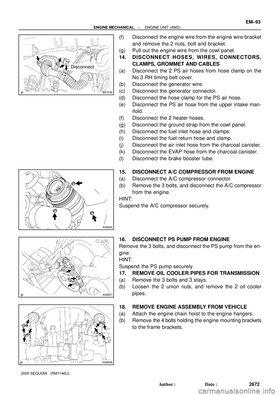
16. DISCONNECT PS PUMP FROM ENGINE
Remove the 3 bolts, and disconnect the PS pump from the en-
gine.
HINT:
Suspend the PS pump securely.
17. REMOVE OIL COOLER PIPES FOR TRANSMISSION
(a) Remove the 3 bolts and 3 stays.
(b) Loosen the 2 union nuts, and remove the 2 oil cooler
pipes.
18. REMOVE ENGINE ASSEMBLY FROM VEHICLE
(a) Attach the engine chain hoist to the engine hangers.
(b) Remove the 4 bolts holding the engine mounting brackets
to the frame brackets.
Page 2683 of 4323

A08936
A08907
A08905
EM±96
± ENGINE MECHANICALENGINE UNIT (4WD)
2675 Author�: Date�:
2005 SEQUOIA (RM1146U)
(d) Install the engine mounting brackets to the frame brack-
ets with the 2 nuts and 4 bolts.
Torque: 38 N´m (388 kgf´cm, 28 ft´lbf)
(e) Remove the engine chain hoist.
3. INSTALL PS PUMP
Install the PS pump with the 3 bolts.
Torque: 17 N´m (175 kgf´cm, 13 ft´lbf)
4. INSTALL A/C COMPRESSOR
(a) Install the A/C compressor with the 3 bolts.
Torque: 49 N´m (500 kgf´cm, 36 ft´lbf)
(b) Connect the A/C compressor connector.
5. CONNECT HOSES, WIRES, CONNECTORS, CLAMPS,
GROMMET AND CABLES
(a) Connect the 2 PS air hoses to hose clamp on the No.3 RH
timing belt cover.
(b) Connect the generator wire.
(c) Connect the generator connector.
(d) Connect the hose clamp for the PS air hose.
(e) Connect the PS air hose to the upper intake manifold.
(f) Connect the 2 heater hoses.
(g) Connect the ground strap to the cowl panel.
(h) Connect the fuel inlet hose and clamps.
(i) Connect the fuel return hose and clamp.
(j) Connect the air inlet hose to the charcoal canister.
(k) Connect the EVAP hose to the charcoal canister.
(l) Connect the brake booster tube.
6. CONNECT ENGINE WIRE TO CABIN
(a) Push into the engine wire through the cowl panel.
Page 2745 of 4323

B16499
Fulcrum
Length
30 cm
SST
B02714
CORRECT
WRONG
Delivery Pipe O±Ring
B04939
Delivery
Pipe
Intake
Manifold O±Ring
Grommet
Injector
Insulator
B17532
Quick Type
Disconnect
B11684
Quick Type
Push
Pull
± SFISFI SYSTEM
SF±3
2737 Author�: Date�:
2005 SEQUOIA (RM1146U)
(3) Using SST, tighten the union bolt to the specified
torque.
SST 09612±24014 (09617±24011)
Torque:
33 N´m (340 kgf´cm, 24 ft´lbf) for use with SST
39 N´m (400 kgf´cm, 29 ft´lbf)
HINT:
Use a torque wrench with a fulcrum length of 30 cm (11.81 in.).
(c) Observe the following precautions when removing or
installing the injectors.
(1) Never reuse the O±ring.
(2) When placing a new O±ring on the injector, take
care not to damage it in any way.
(3) Coat a new O±ring with spindle oil or gasoline be-
fore installing. Never use engine, gear or brake oil.
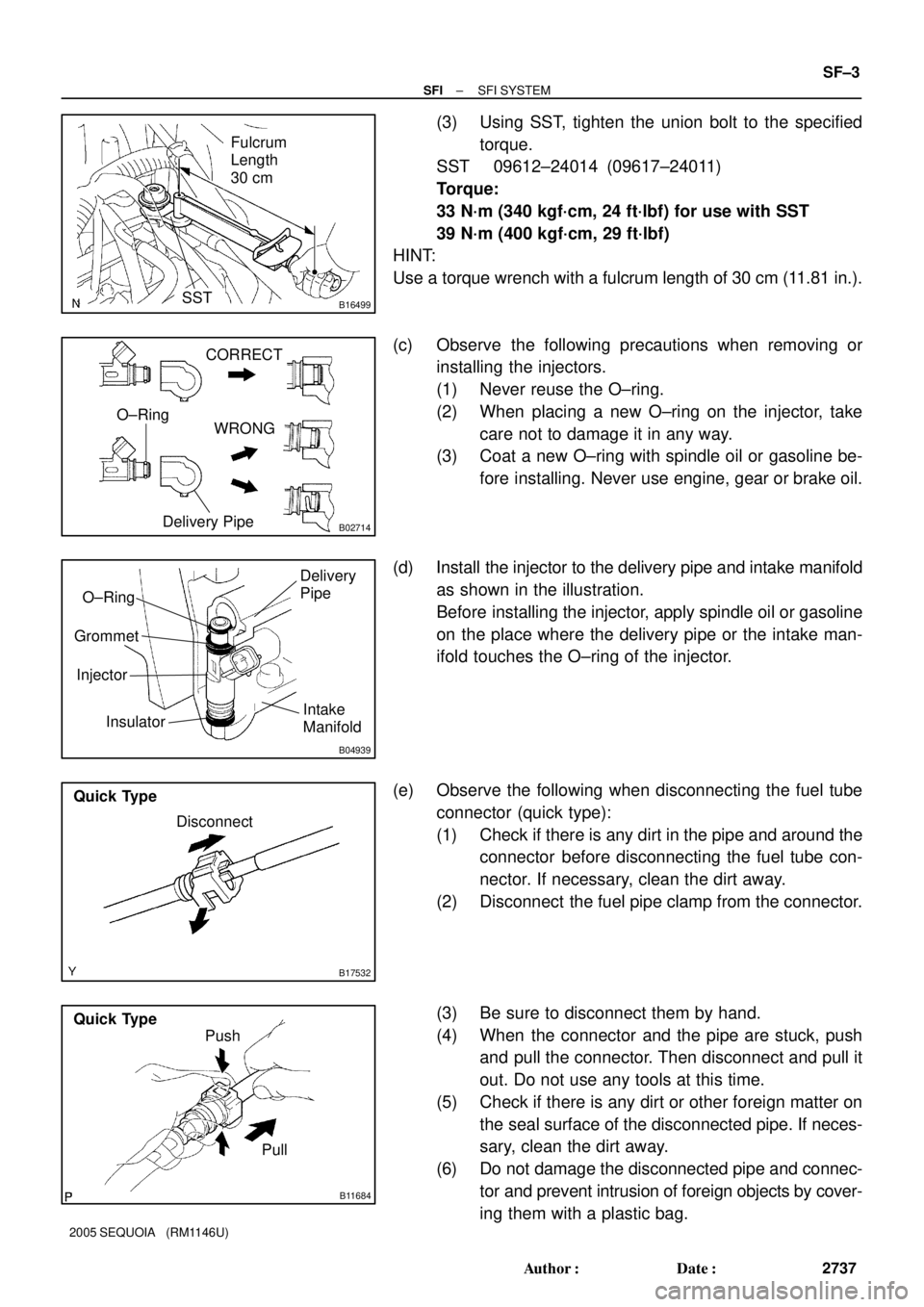
(d) Install the injector to the delivery pipe and intake manifold
as shown in the illustration.
Before installing the injector, apply spindle oil or gasoline
on the place where the delivery pipe or the intake man-
ifold touches the O±ring of the injector.
(e) Observe the following when disconnecting the fuel tube
connector (quick type):
(1) Check if there is any dirt in the pipe and around the
connector before disconnecting the fuel tube con-
nector. If necessary, clean the dirt away.
(2) Disconnect the fuel pipe clamp from the connector.
(3) Be sure to disconnect them by hand.
(4) When the connector and the pipe are stuck, push
and pull the connector. Then disconnect and pull it
out. Do not use any tools at this time.
(5) Check if there is any dirt or other foreign matter on
the seal surface of the disconnected pipe. If neces-
sary, clean the dirt away.
(6) Do not damage the disconnected pipe and connec-
tor and prevent intrusion of foreign objects by cover-
ing them with a plastic bag.
Page 2918 of 4323
AT131±01
D14123
Clutch No.2 (C2) Clutch No.3 (C
3)
Clutch No.1 (C
1)One±way Clutch
No.1 (F1)
One±way Clutch
No.2 (F
2)
Brake No.3
(B
3)
Brake No.1 (B1)
Brake No.2 (B2)One±way Clutch
No.3 (F
3)Brake No.4 (B4)
Shift Solenoid Valve SLT
Shift Solenoid Valve SL1Shift Solenoid Valve S1
Shift Solenoid Valve S2Shift Solenoid Valve SR Shift Solenoid Valve SL2Shift Solenoid Valve SLU
AT±2
± AUTOMATIC TRANSMISSION (A750E, A750F)AUTOMATIC TRANSMISSION SYSTEM
2910 Author�: Date�:
2005 SEQUOIA (RM1146U)
OPERATION
Page 2934 of 4323
AT13B±01
F17895
Steering Wheel Pad
Steering
Wheel
Column Lower
CoverCombination
SwitchSteering Column Assembly
Transmission Control
Cable Assembly
Lower LH Finish PanelColumn Hole
Cover No. 2
No. 2 Universal
Joint Assembly
No. 2 Heater to Register Dust Torx® Screw
35 (360, 26)
35 (360, 26)
8.0 (82, 71 in.´lbf)
26 (260, 19)
26 (260, 19)
8.8 (90, 78 in.´lbf)
50 (510, 37)
8.8 (90, 78 in.´lbf)
Front Door Scuff PlateCowl Side Trim
Hood Lock
Release Lever
8.0 (82, 71 in.´lbf)
Side Panel
No. 2 lntermediate
Shaft AssemblyBrake Pedal
Return Spring
Column Upper Cover
N´m (kgf´cm, ft´lbf): Specified torque
Steering Wheel Lower
No. 3 Cover
Steering Wheel Lower
No. 2 Cover
35 (360, 26)
Siding Yoke
Torx® Screw AT±18
± AUTOMATIC TRANSMISSION (A750E, A750F)COLUMN SHIFT ASSEMBLY
2926 Author�: Date�:
2005 SEQUOIA (RM1146U)
COLUMN SHIFT ASSEMBLY
COMPONENTS