Page 1756 of 4323
I21525
Pushed in Free Stop Light Switch:
DI±1554
± DIAGNOSTICSCRUISE CONTROL SYSTEM
1748 Author�: Date�:
2005 SEQUOIA (RM1146U)
2 Check operation of stop light.
CHECK:
Check that stop lights come on when the brake pedal is depressed, and go off when the brake pedal is re-
leased.
OK:
The stop lights operate normally.
OK Go to step 5.
NG
3 Inspect stop light switch assy.
PREPARATION:
Disconnect the stop light switch assy connector.
CHECK:
Measure the resistance according to the value(s) in the table
below.
OK:
Switch conditionTester connectionSpecified condition
Switch pin free1 ± 4Below 1 W
Switch pin free2 ± 310 kW or higher
Switch pin pushed in1 ± 410 kW or higher
Switch pin pushed in2 ± 3Below 1 W
NG Replace stop light switch assy.
OK
Page 1757 of 4323

4 Check harness and connector (Stop light switch ± battery).
CHECK:
M")
I28460
Wire Harness View:
E4
STP ST1±
± DIAGNOSTICSCRUISE CONTROL SYSTEM
DI±1555
1749 Author�: Date�:
2005 SEQUOIA (RM1146U)
4 Check harness and connector (Stop light switch ± battery).
CHECK:
Measure the voltage according to the value(s) in the table below.
OK:
Tester connectionConditionSpecified condition
S14±4 ± Body groundAlways10 to 14 V
S14±2 ± Body groundIgnition SW ON10 to 14 V
NG Repair or replace harness or connector.
OK
5 Check voltage between terminals STP and ST1± of ECM connector and body
ground.
PREPARATION:
(a) Reconnect the stop light switch connector.
(b) Disconnect the ECM connector.
(c) Turn the ignition switch to the ON position.
CHECK:
Measure the voltage according to the value(s) in the table be-
low.
OK:
Tester connection
(Symbol)ConditionSpecified condition
E4±15 (STP) ±
Body groundBrake pedal depressed10 to 14 V
E4±15 (STP) ±
Body groundBrake pedal releasedBelow 1 V
E4±16 (ST1±) ±
Body groundBrake pedal depressedBelow 1 V
E4±16 (ST1±) ±
Body groundBrake pedal released10 to 14 V
NG Repair or replace harness or connector.
OK
Replace ECM (See page IN±35
).
Page 1805 of 4323
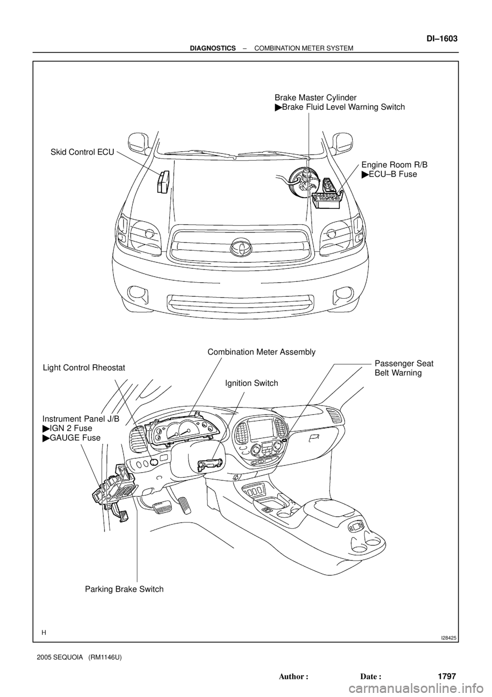
I28425
Brake Master Cylinder
� Brake Fluid Level Warning Switch
Engine Room R/B
� ECU±B Fuse
Light Control RheostatCombination Meter Assembly
Instrument Panel J/B
� IGN 2 Fuse
� GAUGE Fuse
Parking Brake SwitchIgnition Switch
Passenger Seat
Belt Warning
Skid Control ECU
± DIAGNOSTICSCOMBINATION METER SYSTEM
DI±1603
1797 Author�: Date�:
2005 SEQUOIA (RM1146U)
Page 1807 of 4323
DID8P±01
I28566
Seat Position
Control ECU
A/C ECU (Integration
Control Panel) BEANBody ECU
Back Door ECU
ECM
Light Control
Rheostat
Vehicle Speed
Sensor
Oil Pressure
Sender Gauge
Fuel Sender Gauge
Seat Inner
Belt Switch
Park/neutral
Position Switch
Turn Signal
Flasher Relay
Washer Level SensorKey Unlock
Warning Switch
Door Courtesy
Lamp Switch
Parking Brake Switch
Transponder
Key ECU
4WD Control ECU
Airbag Sensor
Center ECU Combination
Meter
Skid Control ECU
Suspension
Control ECU
Translate ECU
Overhead Module
(Garage Door
Opener)BEAN
BEAN
BEAN
BEAN
BEAN BEAN
± DIAGNOSTICSCOMBINATION METER SYSTEM
DI±1605
1799 Author�: Date�:
2005 SEQUOIA (RM1146U)
SYSTEM DIAGRAM
Page 1810 of 4323

SYSTEM DESCRIPTION
1. METER GAUGE AND WARNING/INDICATOR
GAUGE:
ItemDetail
SpeedometerVehicle spe")
DID8Q±01
DI±1608
± DIAGNOSTICSCOMBINATION METER SYSTEM
1802 Author�: Date�:
2005 SEQUOIA (RM1146U)
SYSTEM DESCRIPTION
1. METER GAUGE AND WARNING/INDICATOR
GAUGE:
ItemDetail
SpeedometerVehicle speed sensor (Direct line).
TachometerECM transmits engine speed to the meter to display.
ODO/TRIP MeterCombination meter assy.
FuelDisplays a fuel level according to a signal from the fuel sender gauge (Direct line).
Water TemperatureDisplays engine coolant temperature according to a signal from the ECM (BEAN).
Oil PressureReceives a signal from the oil pressure sender (Direct line).
Volt MeterDisplays vehicle voltage according to a voltage from the IG terminal (Direct line).
WARNING/INDICATOR:
HINT:
Combination meter bulb check is performed for 3 seconds after the ignition switch is turned ON.
ItemDetailList of indicators available for
bulb check
O/D OFFReceives a signal from the ECM (Direct line)±
TURNTurns signal switch ON (Direct line)±
BEAMReceives a signal from the body ECU (*1), Displays a signal received from the
dimmer switch (*2) (Direct line)±
SECURITYReceives a set signal from the transponder key ECU and body ECU (Direct line)±
CHARGEReceives a malfunction signal from the alternator (Direct line)�
AIR BAGReceives a malfunction signal from the airbag sensor center (Direct line)�
D SEAT BELTReceives the driver seat belt signal (Unfastened) from the seat belt inner front LH
(Direct line)±
DOOROpen door indicator comes on when a signal is received from the ECU (BEAN)
from each door±
A/T OIL TEMP.Warning is displayed when the oil temperature is high (Direct line)�
BRAKEComes on when the parking brake switch is on or the brake fluid level warning
switch is on (Direct line)�
MIL (CHECK ENGINE)Receives a malfunction signal from the ECM (Direct line)�
FUEL WARNINGReceives the fuel empty signal from the fuel sender gauge (Direct line)±
ABSReceives a malfunction signal from the skid control ECU (Direct line)�
WASHERWarning is displayed when the washer level is low (Direct line)±
CRUISEReceives a CRUISE on signal or malfunction signal from the ECM (Direct line)±
VSC TRACReceives a malfunction signal from the skid control ECU (Direct line)�
VSC (TRAC) OFFReceives a malfunction signal from the translate ECU (Direct line)�
SLIPReceives a malfunction signal from the translate ECU (Direct line)�
4HIReceives a 4HI signal from the 4WD control ECU (Direct line)±
CTR DIF LOCKReceives a DIF LOCK signal from the 4WD control ECU (Direct line)±
A/T PReceives a P signal from the park/neutral position switch (Direct line)±
A/T NReceives an N signal from the park/neutral position switch (Direct line)±
A/T DReceives a D signal from the park/neutral position switch (Direct line)±
A/T 3Receives a 3 signal from the park/neutral position switch (Direct line)±
A/T 2Receives a 2 signal from the park/neutral position switch (Direct line)±
A/T LReceives an L signal from the park/neutral position switch (Direct line)±
Page 1816 of 4323

PROBLEM SYMPTOMS TABLE
HINT:
Inspect the related ºFuseº and ºRelayº before confirming the su")
DID8U±01
DI±1614
± DIAGNOSTICSCOMBINATION METER SYSTEM
1808 Author�: Date�:
2005 SEQUOIA (RM1146U)
PROBLEM SYMPTOMS TABLE
HINT:
Inspect the related ºFuseº and ºRelayº before confirming the suspected area as shown in the table below.
MALFUNCTION SYSTEM:
SymptomSuspected AreaSee page
Entire combination meter does not operate.Refer to troubleshooting proceduresDI±1628
Operating light control rheostat does not change light brightness.Refer to troubleshooting proceduresDI±1645
Seat belt warning does not operate.Refer to troubleshooting proceduresDI±1650
Key reminder warning buzzer does not sound.
1. Multiplex communication system
2. Key unlock warning switch circuit
3. Door courtesy lamp switch circuit
4. Combination meter assyDI±1892
DI±1715
DI±1728
IN±35
METER GAUGES:
SymptomSuspected AreaSee page
Malfunction in speedometerRefer to troubleshooting proceduresDI±1632
Malfunction in tachometerRefer to troubleshooting proceduresDI±1636
Malfunction in fuel receiver gaugeRefer to troubleshooting proceduresDI±1640
Malfunction in engine coolant temperature receiver gaugeRefer to troubleshooting proceduresDI±1644
Malfunction in oil pressure receiver gaugeRefer to troubleshooting proceduresDI±1654
Malfunction in volt meterRefer to troubleshooting proceduresDI±1658
WARNING LIGHTS:
SymptomSuspected AreaSee page
Check engine warning light (MIL) does not come on.
1. ECM
2. Wire harness or connector
3. Combination meter assyDI±9
±
IN±35
Discharge warning light does not come on.
1. ECM
2. Wire harness or connector
3. Combination meter assyDI±9
±
IN±35
Brake warning light does not come on.
1. Skid control ECU
2. Wire harness or connector
3. Combination meter assyDI±895
±
IN±35
ABS warning light does not come on.
1. Skid control ECU
2. Wire harness or connector
3. Combination meter assyDI±895
±
IN±35
SRS warning light does not come on.
1. Airbag sensor assy
2. Wire harness or connector
3. Combination meter assyDI±1126
±
IN±35
Open door warning light does not come on.
1. Door courtesy light switch circuit
2. Wire harness or connector
3. Combination meter assy
4. Body ECUDI±1728
±
IN±35
IN±35
Fuel level warning light does not come on.
1. Refer to troubleshooting
2. Wire harness or connector
3. Combination meter assyDI±1640
±
IN±35
Low oil pressure warning light does not come on.
1. Low oil pressure warning switch
2. Wire harness or connector
3. Combination meter assyBE±55
±
IN±35
Page 1819 of 4323

(c) Reconnect the C5 and C6 connectors.
(d) Measure the voltage of each terminal of the wire harness side")
± DIAGNOSTICSCOMBINATION METER SYSTEM
DI±1617
1811 Author�: Date�:
2005 SEQUOIA (RM1146U)
(c) Reconnect the C5 and C6 connectors.
(d) Measure the voltage of each terminal of the wire harness side connector.
Standard:
Terminals No.Wiring ColorTerminal DescriptionConditionSpecified Condition
C5±1 ± Body groundR±B ± Body
groundParking brake signalParking brake warning light ON6.7 to 12 V
C5±1 ± Body groundR±B ± Body
groundParking brake signalParking brake warning light OFFBelow 1 V
C5±2 ± Body groundLG±R ± Body
groundCRUISE signalCRUISE indicator light ONBelow 1 V
C5±2 ± Body groundLG±R ± Body
groundCRUISE signalCRUISE indicator light OFF10 to 14 V
C5±3 ± Body groundB ± Body groundIgnition switch signal
(Start)Ignition switch OFFBelow 1 V
C5±3 ± Body groundB ± Body groundIgnition switch signal
(Start)Ignition switch START10 to 14 V
C5±4 ± Body groundG±Y ± Body
groundSeat belt condition signal
(Driver side)D±BELT indicator light ONBelow 1 V
C5±4 ± Body groundG±Y ± Body
groundSeat belt condition signal
(Driver side)D±BELT indicator light OFF10 to 14 V
C5±13 ± Body groundLG±R ± Body
groundWasher level signalWASH LVL indicator light ONBelow 1 V
C5±13 ± Body groundLG±R ± Body
groundWasher level signalWASH LVL indicator light OFF10 to 14 V
C5±14 ± Body groundL±O ± Body
groundO/D OFF indicator signalO/D OFF indicator light ONBelow 1 V
C5±14 ± Body groundL±O ± Body
groundO/D OFF indicator signalO/D OFF indicator light OFF10 to 14 V
C5±15 (*1) ± Body groundY±R ± Body
groundA/T oil temperature signalA/T OIL TEMP. warning light ONBelow 1 V
C5±15 (*1) ± Body groundY±R ± Body
groundA/T oil temperature signalA/T OIL TEMP. warning light OFF10 to 14 V
C5±16 ± Body groundLG±B ± Body
groundSecurity indicator light
signal (Engine immobilizer
system)
Security indicator light ON10 to 14 V
C5±16 ± Body groundLG±B ± Body
groundSecurity indicator light
signal (Engine immobilizer
system)
Security indicator light OFFBelow 1 V
C5±17 ± Body groundGR ± Body
groundSecurity indicator light
signal (Theft deterrent
system)
Security indicator light ON10 to 14 V
C5±17 ± Body groundGR ± Body
groundSecurity indicator light
signal (Theft deterrent
system)
Security indicator light OFFBelow 1 V
C5±18 ± Body groundV±W ± Body
groundCHECK ENGINE signalCHECK ENGINE warning light ONBelow 1 V
C5±18 ± Body groundV±W ± Body
groundCHECK ENGINE signalCHECK ENGINE warning light OFF10 to 14 V
C5±19 ± Body groundG±B ± Body
groundA/T shift position signal
(L)A/T L indicator OFFBelow 1 V
Page 1824 of 4323
I27708
C5±31
C5±32
(*1) C5±30
C5±25
C5±24
C6±10
C5±23
C5±28
C5±21
C5±4
C5±29
C5±26
C6±11
C6±12
C5±22 C5±27
CPU
Supply CircuitC5±6
C5±5
C6±23
HEAD (*2)
OIL MAINT
DOOR
ILL
AIRBAG
D±BELT
FUEL WARNIG
C5±3
HI
N
LO
MAN.
BRAKE C6±16
C6±15
C6±14
C6±13
C5±1
*1: w/ Driving Position Memory *2: USA *3: Canada
TAIL (*3)
ONE STEP
DIMMER Buzzer
LCD
Speedometer
Tachometer
Fuel Gauge
Engine Coolant Temperature
Receiver Gauge
Oil Pressure Gauge
Volt Gauge DI±1622
± DIAGNOSTICSCOMBINATION METER SYSTEM
1816 Author�: Date�:
2005 SEQUOIA (RM1146U)
COMBINATION METER INNER CIRCUIT

 BEANBody ECU
Back Door ECU
ECM
Light Control
Rheostat
Vehicle Speed
Sensor
Oil Pressure
Sender Gauge
Fuel Sender Gau")
 C5±30
C5±25
C5±24
C6±10
C5±23
C5±28
C5±21
C5±4
C5±29
C5±26
C6±11
C6±12
C5±22 C5±27
CPU
Supply CircuitC5±6
C5±5
C6±23
HEAD (*2)
OIL MAINT
DOOR
ILL
AIRBAG
D±B")